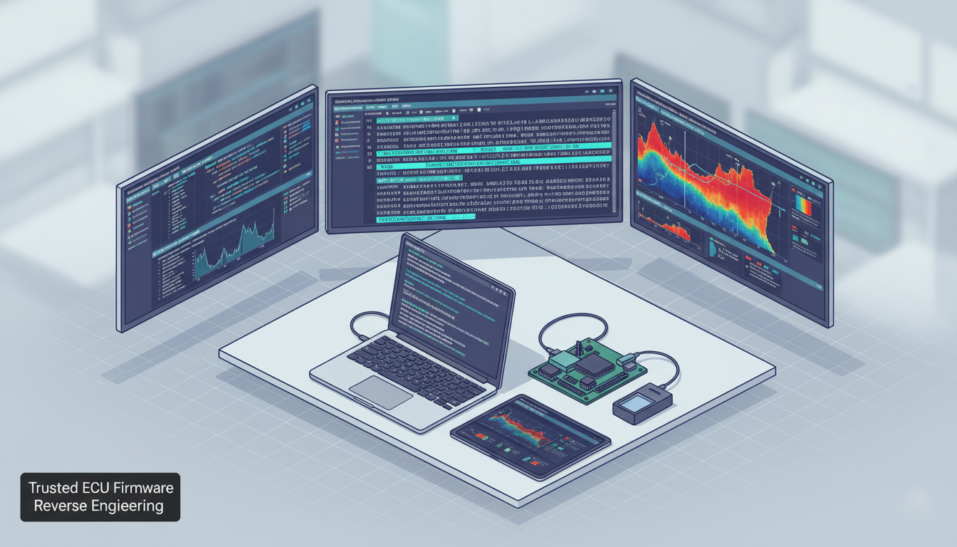
ECU firmware reverse engineering is a rigorous engineering discipline that begins with defensible evidence acquisition and extends through statistical map detection, emulation-backed verification and validated patch delivery. Our approach to ECU firmware reverse engineering emphasizes traceability, reproducibility and safety so that deliverables are suitable for OEMs, workshops and forensic teams.
This article describes a formal engineering workflow for ECU firmware reverse engineering. It is written for OEM engineers, advanced workshops and forensic teams that require defensible, repeatable and auditable processes.
Table of Contents
Engineering, Not Opportunism
Successful ECU firmware reverse engineering is an engineering discipline first and an exercise in curiosity second. Our engagements aim to produce verifiable knowledge about embedded vehicle software while preserving safety, traceability. Whether the scope is calibration extraction for legitimate tuning, forensic reconstruction after an incident, or OEM compatibility validation, our process follows a consistent set of engineering controls: rigorous acquisition, measured static analysis, validated dynamic testing, conservative patch design and comprehensive reporting.
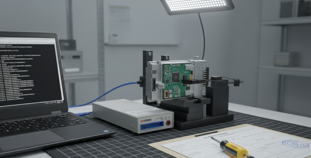
Evidence Acquisition and Chain-of-Custody
Before any technical operation we gate the engagement with administrative and forensic controls. Written authorization, proof of ownership and an acquisition ledger (device images, serial numbers, photographs and signed forms) are required. Firmware and memory images are acquired using the least invasive method that provides a verifiable, bit-for-bit copy: programmer reads (EEPROM/Flash), in-circuit debug (BDM/JTAG/SWD), or, when available and appropriate, manufacturer diagnostic readouts. Each image is hashed (SHA-256 and MD5) and recorded; photographs and timestamps provide physical corroboration. For clients that require forensic-grade output, this chain-of-custody is a deliverable, without it, subsequent analysis cannot be treated as evidentiary.
For authoritative guidance on forensic acquisition and evidence handling, see the NIST digital forensics guide. NIST SP 800-86: Guide to Integrating Forensic Techniques into Incident Response.
Static analysis for ECU Firmware Reverse Engineering

Our static analysis workflows are tuned specifically for ECU firmware reverse engineering: targeted entropy profiling, callgraph recovery and signature-based triage reduce false positives and rapidly surface candidate calibration regions.
Static analysis begins with deterministic setup: the image is loaded into decompilation and disassembly environments (Ghidra, IDA Pro, Binary Ninja) with explicit processor, endianness and memory layout definitions. Different ECU families (RH850, TriCore, MPC5xxx, ARM Cortex cores) bring unique calling conventions and alignment rules; early misconfiguration is a common source of analytic error. We partition the image into bootloader, calibration partitions and communication stacks to focus inspection.
To distinguish calibration regions from code and compressed blobs, we apply statistical heuristics sliding-window entropy profiling, autocorrelation measures and monotonicity checks. Calibration tables typically present low local entropy, structured repetition and predictable numeric ranges. Cross-references and callgraph reconstruction expose likely security routines, communication handlers and checksum code; candidate data regions are exported for visual inspection in calibration viewers (WinOLS/TunerPro) and further validated via telemetry correlation where dynamic access is available.
For tooling and decompilation references we often rely on open analysis suites; see Ghidra (official site) for documentation and downloads.
Map Detection and Calibration Map Extraction Techniques
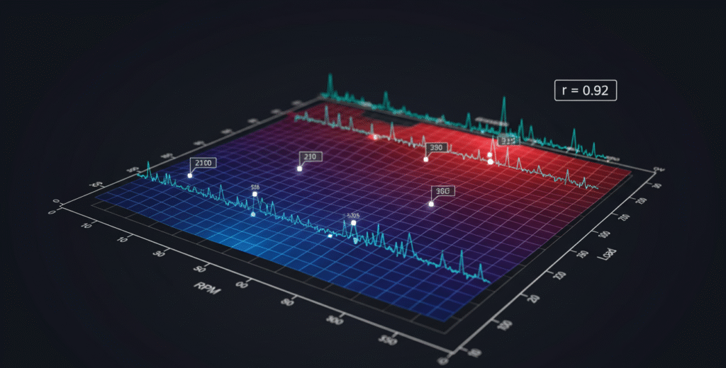
Calibration map extraction combines structural heuristics with telemetry correlation to produce axis inference that is reproducible and verifiable for further tuning or forensic analysis.
Identifying a memory block as a calibration map is only the first step; axis inference determining whether table rows or columns correspond to RPM, load, temperature or other signals is essential for safe modification. We treat axis inference as a data-science problem: synchronized telemetry (CAN/UDS) captured while exercising the ECU under controlled conditions is correlated against sampled values from candidate memory offsets. Statistical measures Pearson correlation, cross-correlation with lag analysis, and repeated-sample confidence intervals produce confidence scores for axis hypotheses. When telemetry is unavailable, structural properties (monotonic cell progression, typical axis ranges, and known OEM constants) provide a secondary basis for inference. Our deliverable includes per-axis confidence metrics (e.g., RPM: 0.92 confidence), which aid conservative decision-making during downstream patching.
For background on calibration formats and industry practices (useful when inferring axes) see high-level standards such as ISO/SAE 21434 (Automotive cybersecurity overview).
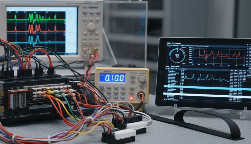
Dynamic analysis and bench testing: validating hypotheses
Static hypotheses must be validated in runtime conditions. Bench rigs configured with controlled power supplies, sensor simulators and harnesses recreate vehicle signals without the risks of on-road testing. We run staged tests boot and communications checks, restricted dynamic experiments to confirm map behavior, and safety-monitored stress tests. Runs capture synchronized CAN/UDS traces, telemetry and when available runtime memory snapshots. Time-aligned telemetry and memory samples allow robust verification that specific memory offsets drive observed behavior; this is the practical method for confirming map interpretations and for validating axis inferences.
Emulation and code execution: safe, isolated verification
Emulation frameworks (Unicorn Engine, QEMU variants) permit isolated execution of routines and accelerate function discovery. We construct minimal emulation harnesses that mimic peripheral state and execute candidate functions with controlled inputs, monitoring register and memory outputs. Emulation is a powerful tool for checksum detection and logic validation, but emulator fidelity must be validated against hardware; timing-sensitive peripherals or hardware-dependent side-effects can produce discrepancies. We therefore always corroborate emulation findings with selective bench runs.
Checksum and signature analysis: identifying and respecting integrity protections
Checksum and signature protections constitute the most consequential technical and legal constraints. Our layered approach first locates candidate checksum routines by identifying data-iteration patterns tight loops reading buffers and producing compact digests then uses emulation over controlled inputs to compare outputs against known checksum families (CRC variants, Fletcher-type, simple additive checks). When a standard checksum is identified, we implement compatible recomputation in the patch pipeline. In the presence of asymmetric signatures or challenge/response verification (frequently observed in UDS 0x27 flows), we document the required re-signing constraints and present legitimate remediation options: OEM-authorized re-signing, bootloader replacement under OEM cooperation, or hardware replacement strategies. The priority is to present risk-aware, lawful paths rather than promote ad hoc circumvention.
Patch strategy and non-destructive implementation
Patching strategy follows a preserve-and-redirect principle. Wherever practical we avoid destructive in-place edits by implementing small trampolines or redirecting call sites to modified logic located in unused image regions. This preserves the original image, enables rollback and simplifies verification. Every patch is versioned and accompanied by a detailed changelog that lists offsets, rationale and test vectors. Before any flash operation we produce and hash-verify a rollback image and a flashing SOP that outlines programmer model, pinout, voltage tolerances, ESD precautions and explicit rollback commands. The SOP is both a technical and a safety artifactNincorrect flashing parameters are a leading cause of irrecoverable hardware damage.
Safe flashing, hardware considerations and ESD control
Flashing is the highest-risk operation. We confirm programmer compatibility (SOIC clip, BGA socketing, etc.), use current-limited power supplies and surge protection, and enforce ESD-safe bench protocols. Pre-flash checks include original image hash verification, sanity checks on the patched image and verification of the rollback image. Only once all checks pass do we proceed; the entire flash event is time-stamped and documented for traceability.
Validation and Bench Testing in ECU Firmware Reverse Engineering
Validation is multi-tiered and metrics-driven. Bench test suites exercise the operational envelope and engineered failure modes, each with pre-defined pass/fail criteria measured by telemetry thresholds and DTC behavior. Regression comparisons quantify changes and detect unintended side-effects such as DTC inflation or limp-home triggers. On-vehicle verification follows only after successful bench validation and explicit client authorization; sessions are executed under controlled conditions with experienced drivers and recorded telemetry. The objective is to confirm controlled behavior changes, not to pursue extreme performance without consideration of safety and compliance.
Deliverables: what clients receive and why it matters
A professional delivery bundle contains both technical artifacts and managerial documentation. Typical deliverables include hashed original and patched images, annotated disassembly with labelled offsets, a verified address map, extracted calibration artifacts (CSV/XDF), CAN/UDS captures, the flashing SOP, and a comprehensive technical report describing methodology, assumptions and limitations. For forensic engagements chain-of-custody records and acquisition photographs are included as discrete artifacts suitable for third-party review. Deliverables are versioned and stored in a controlled repository to enable reproducibility and peer review.
Tooling and automation: augmenting engineers, not replacing them
Tool selection is use-case dependent. We use Ghidra and IDA Pro for deep static analysis, WinOLS and TunerPro for calibration visualization, professional CAN interfaces and logging tools for runtime capture, and industry-standard programmers for flashing. Bespoke automation scripts reduce repetitive tasks—signature scanning, candidate table ranking and axis-correlation analytics—and include unit tests and confidence checks. For statistical inference tasks such as axis detection we favor repeated sampling and confidence intervals to reduce false positives.
For professional CAN capture and analysis hardware consider vendors such as Vector and Kvaser, which provide industry-grade interfaces and logging tools.
Version control, reproducibility and artifact management
All images, scripts, test logs and intermediate artifacts are stored in a version-controlled repository with immutable hash metadata and access controls. Telemetry and logs are archived in machine-readable formats to support automated regression comparisons and enable long-term forensic analysis. This practice supports reproducibility, peer review, and controlled handover.
Communication, reporting and governance
Technical findings are paired with executive summaries that frame risk and impact for business stakeholders. Deliverables begin with a feasibility memo that documents acquisition options, blocking issues (signed partitions, unavailable keys) and a realistic timeline. This memo reduces scope creep and aligns expectations. Regular progress updates and the final report provide traceability and support decision-making.
Practical examples and conceptual pseudocode (non-exploitative)
For illustration only these conceptual snippets describe detection logic without enabling circumvention:
# Candidate checksum function detector - conceptual
for function F in disassembly:
    if detect_data_iteration(F):
        samples = generate_random_samples(N)
        outputs = [emulate(F, s) for s in samples]
        if outputs_are_compact(outputs):
            mark_as_checksum_candidate(F)

# Axis inference - conceptual
for candidate_table T in memory_regions:
    sample_positions = sample_cells(T, K)
    telemetry_series = collect_synchronized_telemetry()
    correlations = {}
    for signal in telemetry_series:
        correlations[signal] = compute_correlation(sample_positions, telemetry_series[signal])
    assign_axes_based_on_max_correlation(correlations)
Operational recommendations for clients
Provide as much context as possible at intake: BIN/HEX images, CAN/UDS logs, ECU photos and any prior artifacts. Early access to a donor vehicle or bench harness shortens discovery. For forensic or OEM work define evidence-handling procedures up front. These measures reduce discovery time and produce defensible, reproducible results.
Conclusion: disciplined engineering, auditable outcomes
Professional ECU reverse engineering requires a disciplined, auditable approach that balances technical rigor with safety and compliance. By applying rigorous acquisition, statistical map detection, emulation-backed verification, conservative patching and structured validation, teams can deliver repeatable outcomes that satisfy OEMs, workshops and forensic clients. If you would like a downloadable methodology PDF, sample redacted artifacts (hashed), or automation scripts for candidate detection that are unit-tested and documented, contact our team and we will prepare forensic-grade deliverables.
Request a feasibility assessment or sample deliverable:
© ReverseEngineer.net | Professional ECU Firmware Reverse Engineering & Analysis
Let's Work Together
Need Professional Assistance with Reverse Engineering or Cybersecurity Solutions? Our Team is Ready To Help You Tackle Complex Technical Challenges.