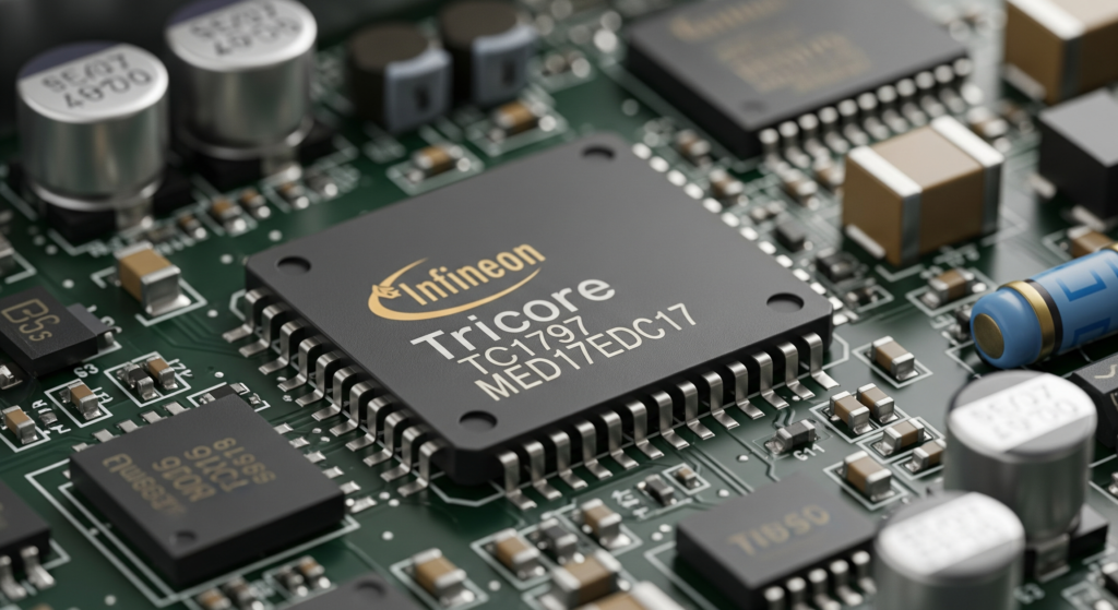
The Bosch MED17 (gasoline) and EDC17 ECU (diesel) families represent one of the most widely deployed engine management platforms in modern automotive history. Found across Volkswagen Group, BMW, Mercedes-Benz, Hyundai-Kia, Fiat, Ford, and dozens of other manufacturers, these Infineon Tricore-based controllers manage everything from direct fuel injection timing to turbocharger boost pressure, exhaust gas recirculation, and emissions compliance strategies.
Despite their ubiquity, detailed technical resources for reverse engineering these ECUs remain surprisingly scarce. Most publicly available information is either superficial, scattered across fragmented forum posts, or locked behind expensive commercial tool ecosystems. This guide aims to change that by providing a structured, authoritative methodology for approaching Bosch MED17 and EDC17 firmware analysis from first principles.
Whether you are a calibration engineer, an automotive security researcher, a forensic investigator examining Dieselgate-style defeat devices, or an advanced tuner seeking to understand what lies beneath the abstraction of commercial tuning tools, this guide provides the foundational knowledge you need.
UNDERSTANDING THE MED17 AND EDC17 PLATFORM ARCHITECTURE
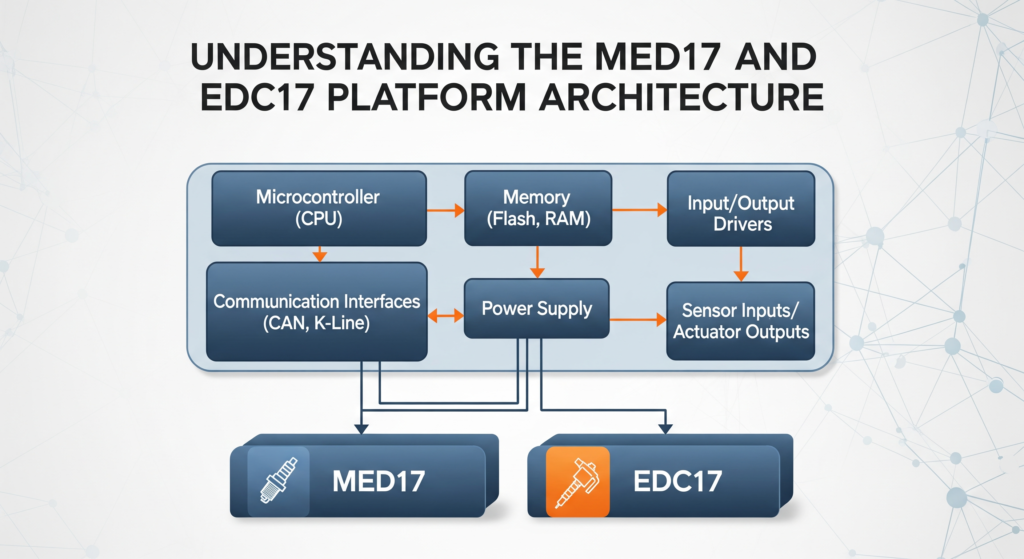
Before touching any firmware, it is essential to understand what you are dealing with at the hardware level. The Bosch MED17 and EDC17 are not single ECU designs but rather platform families encompassing dozens of hardware variants. The designation following the family name – for example, MED17.5.2 or EDC17C46 – specifies the exact hardware configuration, which determines the processor variant, flash memory size, peripheral configuration, and pinout.
The Bosch MED17 family handles gasoline direct injection (GDI) applications. The “M” stands for Motronic, Bosch’s long-running gasoline engine management brand, and “ED” signifies electronic diesel. The “17” generation number indicates the Tricore-based architecture that succeeded the earlier ME7.x (C16x-based) and MED9.x families.
Key hardware parameters that vary across subvariants include:
- Infineon Tricore processor model (TC1766, TC1767, TC1793, TC1796, TC1797, TC1782, TC1784)
- Internal flash size (typically 2 MB to 4 MB of program flash)
- External flash presence and type (some variants add external NOR flash)
- Data flash (DFLASH) size for adaptive learning values
- RAM allocation
- Number of CAN bus interfaces
- Analog input channels and resolution
Understanding which Tricore variant your specific ECU uses is the critical first step, because it dictates the memory map, the boot mode entry procedure, the debug interface availability, and the applicable extraction technique.
INFINEON TRICORE ARCHITECTURE ESSENTIALS FOR REVERSE ENGINEERS
The Infineon Tricore is a 32-bit microcontroller architecture specifically designed for automotive powertrain applications. It is a hybrid architecture combining a RISC processor core for general computation, a DSP-like pipeline for signal processing tasks (such as crank angle calculations), and a dedicated microcontroller peripheral bus. This three-way design is where the “Tri” in Tricore originates.
Memory Architecture
Tricore uses a unified 32-bit address space, but the physical memory is segmented into distinct regions. For MED17/EDC17 reverse engineering, the critical memory regions are:
- Program Flash (PFLASH): Starting at 0x80000000 (cached) or 0xA0000000 (non-cached), this is where the main firmware code and calibration data reside. Sizes range from 2 MB to 4 MB depending on the variant. PFLASH is divided into physical sectors of varying sizes, typically with smaller sectors (16 KB) at the bottom for the bootloader and larger sectors (256 KB) in the upper region for the application firmware.
- Data Flash (DFLASH): Starting at 0xAF000000, this is an EEPROM-emulation flash region used to store adaptive values, learned parameters, fault codes, mileage counters, immobiliser data, and other non-volatile runtime data. Typical sizes are 64 KB to 128 KB.
- Boot ROM: Starting at 0xAFFFC000, this is a factory-programmed mask ROM containing Infineon’s Bootstrap Loader (BSL). This ROM is critical for boot mode firmware extraction, as it implements the serial bootstrap protocol.
- SRAM: Starting at 0xD0000000, volatile working memory ranging from 56 KB to 136 KB. During reverse engineering, SRAM contents captured via debug interfaces can reveal runtime state including decrypted keys and intermediate computation values.
- Peripheral Control Registers: Mapped in the 0xF0000000 region, these registers control the CAN modules, ADC, timers, GPIOs, and DMA controllers. Understanding the peripheral register layout is essential for identifying what the firmware is actually controlling.
Register Model
Tricore provides 16 data registers (D0-D15) and 16 address registers (A0-A15). Address register A10 serves as the stack pointer, and A11 serves as the return address register (link register). The processor uses a Context Save Area (CSA) mechanism for function calls and interrupts, which differs significantly from the conventional stack-based calling conventions found in ARM or x86. When reversing decompiled output in Ghidra or IDA Pro, understanding this CSA mechanism helps explain unusual-looking function prologues and epilogues.
Instruction Set Considerations
Tricore instructions are either 16-bit or 32-bit, with the processor automatically distinguishing between them based on encoding. This variable-length encoding can occasionally trip up disassemblers if the initial analysis entry point is misaligned. When loading a raw binary into Ghidra, ensuring correct base address alignment and entry point specification is critical for clean disassembly.
FIRMWARE STRUCTURE AND MEMORY LAYOUT IN MED17/EDC17
A typical Bosch MED17 or EDC17 firmware image (whether extracted via JTAG, boot mode, or OBD bench read) contains several distinct logical zones within the PFLASH region. Understanding this layout is fundamental to productive reverse engineering.
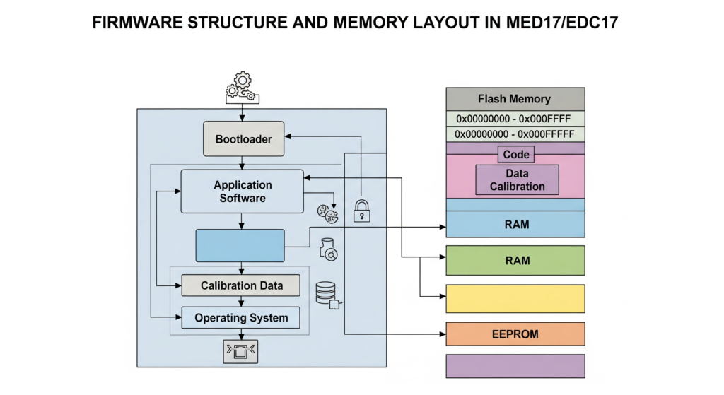
Bootloader Region (BSW — Basic Software Bootloader)
The first portion of PFLASH, typically the first 64 KB to 128 KB starting at 0x80000000, contains the Bosch bootloader. This code handles:
- Hardware initialization (clock configuration, watchdog setup, memory controller initialization)
- UDS (Unified Diagnostic Services) communication stack for reflashing via OBD
- SecurityAccess (Service 0x27) seed-key authentication for reprogramming authorization
- Flash programming routines
- Boot integrity checks
The bootloader is often protected separately from the application firmware. In many variants, the bootloader flash sectors have independent read/write protection bits that are set during manufacturing. This is why some extraction methods can read the application firmware but not the bootloader, and vice versa.
Application Software (ASW)
The bulk of the firmware is the application software, typically spanning from around 0x80020000 to 0x80180000 or higher. This contains:
- The AUTOSAR (or pre-AUTOSAR) operating system and runtime environment
- Signal processing chains for all sensor inputs
- Control algorithms (PID controllers, state machines, lookup table interpolation routines)
- Diagnostic routines (DTC management, OBD-II readiness monitors)
- Communication stacks (CAN, LIN, FlexRay depending on variant)
- Immobiliser authentication routines
- Anti-tampering and integrity monitoring code
Calibration Data Zone
This is the region of highest interest for tuning and forensic analysis. The calibration data zone contains all the parameter tables, maps, scalars, and constants that define the specific vehicle application. This includes:
- Fuel injection maps: Relating engine RPM, load (manifold pressure or air mass), and injection duration or fuel mass
- Ignition timing maps: (MED17 only) Spark advance as a function of RPM and load
- Boost pressure target maps: Desired turbocharger boost vs RPM and accelerator position
- Torque limitation tables: Maximum torque as a function of RPM, gear, temperature
- EGR (Exhaust Gas Recirculation) maps: EGR valve position targets
- Lambda/AFR targets: Desired air-fuel ratios across the operating envelope
- DPF regeneration parameters: (EDC17) Soot loading thresholds, regeneration temperatures
- Smoke limiter tables: (EDC17) Maximum fueling to limit visible smoke
- Temperature correction tables: Compensations for intake air temp, coolant temp, fuel temp
The calibration zone is typically located in the upper portion of PFLASH and can be identified by its distinct binary pattern: while code regions show high entropy with frequent branching patterns, calibration data tends to appear as structured arrays of 8-bit or 16-bit values with gradual gradients visible in hex or binary visualization tools.
A practical technique for quickly locating the calibration zone boundary is to use binary entropy analysis. Tools such as binwalk -E or custom Python scripts using sliding-window Shannon entropy calculations will show a clear transition point where code entropy (typically 5.5-7.0 bits/byte) drops to data entropy (typically 3.0-5.5 bits/byte).
Calibration Zone Identification via A2L/ODX Metadata
In professional reverse engineering scenarios, the most efficient path to understanding calibration data layout is through A2L files. The A2L (ASAM MCD-2MC) file format is an industry-standard metadata description that maps every calibration parameter to its exact memory address, data type, conversion formula, axis definitions, and physical units.
While A2L files are proprietary and not publicly distributed, they do occasionally become available through various channels. If an A2L file matching your firmware version is available, it transforms the reverse engineering process from blind binary analysis into systematic parameter identification. Tools like INCA (from ETAS), CANape (from Vector), or the open-source asamint library can parse A2L files.
Without an A2L file, the reverse engineer must rely on binary pattern recognition, cross-referencing known map structures from related firmware versions, and systematic analysis of the code that references calibration addresses.
FIRMWARE EXTRACTION METHODS FOR Bosch MED17/EDC17
Extracting the firmware from the ECU is the prerequisite for any analysis. The Tricore platform supports several extraction vectors, each with different trade-offs in terms of invasiveness, completeness, and difficulty.
Boot Mode (BSL) Extraction
The Tricore Bootstrap Loader, burned into mask ROM at the factory, provides a UART-based serial protocol for reading and writing flash memory. Boot mode is activated by pulling specific pins to defined logic levels during a power-on reset. The exact pin configuration varies by Tricore variant:
- TC1766/TC1767: Typically involves holding specific port pins high/low during reset
- TC1797: Uses the HWCFG pins to select BSL entry
Boot mode extraction requires physical access to the ECU PCB and soldering to the appropriate test points. On many MED17/EDC17 boards, Bosch has intentionally removed or obscured the BSL access points, requiring careful PCB analysis to locate the correct pads.
Advantages: Does not require expensive debug hardware. Works even if the JTAG interface is locked.
Disadvantages: Requires PCB-level work. Bosch has implemented BSL password protection on newer variants, meaning the BSL will demand an 8-byte password before granting access.
JTAG/DAP Extraction
Tricore processors implement a debug interface based on the OCDS (On-Chip Debug Support) standard, accessible through a JTAG-compatible connector. Using a suitable debug probe (such as a Lauterbach TRACE32, PLS UDE, iSYSTEM winIDEA, or a lower-cost adapter), the entire flash memory can be read through the debug interface.
Advantages: Provides the most complete dump including bootloader, application, and data flash. Allows live debugging, breakpoint setting, and runtime memory inspection.
Disadvantages: Many Bosch MED17/EDC17 units ship with the JTAG interface locked via the OCDS password or device security features. Unlocking may require the correct password or exploiting implementation weaknesses.
OBD-Based Bench Read (via UDS/KWP2000)
Some commercial tools perform firmware reading through the standard OBD diagnostic port using the ECU’s own diagnostic protocol. This approach leverages either:
- Legitimate ReadMemoryByAddress (UDS Service 0x23) after successful SecurityAccess authentication
- Exploits in the bootloader’s update protocol
- Manufacturer-specific extended diagnostic services
Advantages: Non-invasive, no PCB work required. Fast and repeatable.
Disadvantages: Typically does not provide a complete dump (bootloader region is often excluded). Relies on knowing or bypassing the SecurityAccess seed-key algorithm. May not work on all variants or firmware versions.
For a detailed comparison of all hardware extraction interfaces, see our companion guide: ECU Firmware Extraction Methods: JTAG, BDM, SWD & Boot Mode Compared
Need professional firmware extraction?
Our engineers maintain a lab equipped with Lauterbach, PLS, and custom boot mode tooling for all major MED17 and EDC17 variants. Contact our ECU reverse engineering team.
SETTING UP A TRICORE REVERSE ENGINEERING ENVIRONMENT
Ghidra Configuration for Tricore
Since version 10.1, Ghidra includes native Tricore processor support. To set up an effective analysis environment:
- Create a new project and import the raw firmware binary using File -> Import File
- Set the language to “Tricore:LE:32:default” (little-endian 32-bit)
- Configure the base address to match the physical flash origin — typically 0x80000000 for PFLASH dumps or 0xA0000000 if dumped from the non-cached window
- Define memory blocks to map the full address space. Create separate blocks for PFLASH, DFLASH, SRAM, Boot ROM, and peripheral registers. Even if you only have the PFLASH dump, defining the other regions as uninitialized helps Ghidra resolve cross-references
- Set the entry point at the reset vector. For Tricore, the reset vector is at 0x80000020 (the Boot Mode Header Table, or BMHD, at the start of PFLASH contains the entry point address)
After initial auto-analysis, Ghidra will identify thousands of functions. The quality of the initial analysis depends heavily on correct base address configuration. If functions appear fragmented or references point to invalid addresses, verify your base address alignment.
IDA Pro with Tricore Plugin
IDA Pro supports Tricore through its built-in processor module. The workflow is similar: load the binary, specify Tricore as the processor, set the correct ROM start address, and let the auto-analysis run. IDA Pro’s Tricore support is mature and generally produces reliable disassembly.
For advanced analysis, the Hex-Rays decompiler plugin for Tricore can generate pseudo-C code from the firmware, dramatically accelerating the understanding of complex control algorithms.
Binary Ninja and Other Tools
Binary Ninja supports Tricore through community plugins. While less mature than the Ghidra or IDA solutions, it offers a modern interface and scriptable analysis pipeline that some researchers prefer.
Regardless of the tool chosen, supplementing the disassembler with Tricore architecture documentation from Infineon (now available from Infineon’s website as the “Tricore Architecture Manual” and the specific user manual for your TC17xx variant) is indispensable. The peripheral register definitions, interrupt vector tables, and memory protection unit configurations documented in these manuals are essential references during analysis.
NAVIGATING THE FIRMWARE: KEY ANALYSIS STRATEGIES
With thousands of functions in a typical Bosch MED17/EDC17 firmware, knowing where to focus your analysis is critical.
String-Based Landmark Identification
Even in stripped binaries without symbol information, Bosch MED17/EDC17 firmware contains diagnostic-related strings that serve as landmarks. Search for:
- UDS service-related strings and error messages
- DTC (Diagnostic Trouble Code) definition strings
- AUTOSAR module identifiers
- Calibration parameter name fragments (some firmware versions embed partial A2L references)
These strings provide anchor points from which you can trace references backward to locate the containing functions and understand the surrounding code structure.
Interrupt Vector Table Analysis
The Tricore interrupt vector table, located at the Base Interrupt Vector Table (BIV) address configured during startup, maps hardware interrupts to their handler functions. Identifying the handlers for CAN receive interrupts, ADC completion interrupts, and timer interrupts reveals the core real-time processing loops of the engine management system.
Map Lookup Function Identification
One of the most valuable analysis targets is the set of functions that perform table lookups and interpolation. MED17/EDC17 firmware uses standardized lookup routines for:
- 1D curve interpolation (single-axis lookup)
- 2D map interpolation (bilinear interpolation on two-axis maps)
- 3D volume interpolation (less common, trilinear)
These functions have distinctive signatures: they take axis descriptor pointers and data array pointers as arguments, perform boundary clamping, calculate interpolation fractions, and return the interpolated result. Once you identify and label these lookup functions, every cross-reference to them reveals a calibration map access, allowing you to systematically catalog all maps used in the firmware.
A typical 2D map lookup in Tricore pseudocode follows a pattern of: load X-axis breakpoint array, binary search for the input value’s position, calculate the fractional position between breakpoints, repeat for the Y-axis, then perform bilinear interpolation across the four nearest map cells. Recognizing this pattern across the firmware is a high-leverage reverse engineering skill.
CHECKSUM AND INTEGRITY VERIFICATION
Bosch MED17/EDC17 firmware employs multiple layers of integrity checking that must be understood and correctly handled during any modification.
CRC32 Block Checksums
The firmware is divided into logical blocks, each protected by a CRC32 checksum. The checksum descriptor table (typically located at a fixed offset within the calibration zone or at the end of the application software) lists the start address, length, and expected CRC value for each protected region. After any calibration modification, the corresponding CRC values must be recalculated and written back to the descriptor table.
RSA Digital Signatures
Modern Bosch MED17/EDC17 variants (approximately 2012 onward) implement RSA-2048 or RSA-4096 digital signature verification of the firmware. The ECU stores the public key (or a hash of the public key), and the firmware image includes an RSA signature block. During boot, the bootloader verifies the application software’s RSA signature before transferring control.
RSA signature verification represents a fundamentally stronger protection than CRC checksums. Unlike CRC correction, which is a straightforward recalculation, bypassing RSA verification requires either obtaining the private signing key (infeasible without a catastrophic key compromise) or modifying the signature verification code itself. Analysis of how the RSA verification is implemented and whether any weaknesses exist in a specific variant’s implementation is an advanced reverse engineering task.
For a comprehensive treatment of checksum and CRC analysis techniques, see our dedicated guide: Understanding ECU Checksum & CRC Algorithms: A Reverse Engineer’s Guide
Runtime Integrity Monitoring
Beyond boot-time checks, many MED17/EDC17 firmwares implement periodic runtime integrity monitoring. Background tasks continuously recalculate checksums over critical memory regions and trigger fault reactions (limp mode, engine shutdown, DTC storage) if tampering is detected. Understanding these runtime monitors is essential for any persistent firmware modification.
Facing checksum or signature challenges? Our team has extensive experience with MED17/EDC17 integrity mechanisms across hundreds of variants. Get expert assistance
PRACTICAL ANALYSIS WORKFLOW: PUTTING IT ALL TOGETHER
A structured approach to MED17/EDC17 reverse engineering follows this general sequence:
- Identify the exact ECU variant from the hardware part number, software version, or PCB markings. Cross-reference against known Tricore processor mappings.
- Extract the firmware using the most appropriate method for your variant and objective. Verify the dump integrity by checking for known patterns at expected offsets.
- Load into your analysis tool with correct Tricore processor selection and base address. Run auto-analysis and wait for completion.
- Locate landmark functions using string references, interrupt vector analysis, and known pattern matching. Label these functions to establish a reference framework.
- Identify the calibration zone using entropy analysis, binary visualization, and cross-references from map lookup functions. Document the boundaries and any A2L correlation data available.
- Analyze specific subsystems based on your objective — whether that is understanding the fueling strategy, investigating an emissions defeat device, or characterizing the security implementation.
- Document your findings systematically. Firmware reverse engineering is iterative, and maintaining clear notes on identified functions, data structures, and cross-references dramatically accelerates future work on related variants.
The Bosch MED17 and EDC17 platform represents both a significant reverse engineering challenge and a rich target for technical analysis. The Tricore architecture, while less documented in the public reverse engineering community than ARM or x86, is well-supported by modern tools including Ghidra’s native Tricore module. The structured approach outlined in this guide — from hardware identification through firmware extraction, environment setup, and systematic binary analysis — provides a replicable methodology applicable across the many subvariants within these ECU families.
The depth of engineering embedded in these controllers is substantial. Every calibration map, every control algorithm, and every security mechanism reflects decades of Bosch’s powertrain control expertise. Approaching this work with both technical rigor and appropriate respect for the complexity involved will yield the most productive results.
Ready to accelerate your MED17 or EDC17 reverse engineering project? Whether you need firmware extraction, calibration analysis, security research, or forensic investigation, our team brings years of hands-on Tricore ECU experience to every engagement. Contact ReverseEngineer.Net today
Let's Work Together
Need Professional Assistance with Reverse Engineering or Cybersecurity Solutions? Our Team is Ready To Help You Tackle Complex Technical Challenges.