What Is CAN Bus and Why Reverse Engineer It?
CAN bus (Controller Area Network) is the backbone communication protocol in modern vehicles. Every electronic control unit in a car, from the engine ECU and transmission controller to the ABS module and instrument cluster, exchanges data over one or more CAN bus networks. Despite its critical role, CAN bus communication is proprietary and undocumented by manufacturers. This is exactly why reverse engineering these networks has become an essential discipline for automotive security researchers, performance tuners, and diagnostic tool developers.
When you connect to a vehicle’s OBD-II port and start capturing traffic, you see a stream of hexadecimal messages flying by at high speed. Without reverse engineering, these messages are meaningless. CAN bus reverse engineering is the process of identifying which ECU sends each message, what each byte represents, and how to interpret or manipulate the data to achieve a specific goal.
This guide covers the complete CAN bus reverse engineering workflow: from protocol fundamentals and hardware setup to message identification techniques, UDS diagnostic services, and real-world applications in ECU development and automotive security.
CAN Bus Protocol Fundamentals
Before diving into reverse engineering, understanding the CAN protocol structure is essential. CAN was developed by Bosch in the 1980s and became the standard for in-vehicle networking. It uses a differential two-wire bus (CAN-H and CAN-L) with multi-master arbitration, meaning any node can transmit at any time, and message priority is determined by the arbitration ID.
CAN Frame Structure
Every CAN message follows a standard frame format. Understanding this structure is the first step in CAN bus reverse engineering:
| Field | Bits | Description |
|---|---|---|
| Arbitration ID | 11 (standard) or 29 (extended) | Message identifier and priority. Lower ID = higher priority. |
| DLC | 4 | Data Length Code. Number of data bytes (0-8). |
| Data | 0-64 (0-8 bytes) | The payload. Contains sensor values, commands, or diagnostic data. |
| CRC | 15 | Cyclic Redundancy Check for error detection. |
| ACK | 2 | Acknowledgment slot. Receiving nodes confirm receipt. |
CAN Bus Speeds and Networks
Modern vehicles typically run multiple CAN networks at different speeds:
- High-speed CAN (500 kbps): Powertrain network connecting the engine ECU, transmission, ABS, and other safety-critical modules.
- Medium-speed CAN (250 kbps): Comfort and body electronics, including door modules, climate control, and seat controllers.
- Low-speed CAN (125 kbps): Infotainment and diagnostic systems.
- CAN-FD (up to 8 Mbps): Flexible Data-rate CAN, supports up to 64 bytes per frame. Increasingly common in 2020+ vehicles.
When performing CAN bus reverse engineering, identifying which network carries the data you need is the first practical step. The OBD-II port typically provides access to the high-speed powertrain CAN, but accessing body or comfort networks may require tapping into wiring behind the dashboard or at specific ECU connectors.
OBD-II vs Raw CAN: Understanding the Access Points
Many people confuse OBD-II with CAN bus, but they are different layers. OBD-II (On-Board Diagnostics) is a standardized diagnostic protocol that runs on top of CAN. It defines a specific set of services (PIDs) for emissions-related data like engine RPM, coolant temperature, and oxygen sensor readings.
Raw CAN bus traffic, on the other hand, contains everything: proprietary manufacturer messages for steering angle, brake pressure, throttle position, gear selection, window status, and hundreds of other signals that OBD-II does not expose. This is where CAN bus reverse engineering becomes valuable, because the real data lives in the raw CAN stream, not in the limited OBD-II layer.
| Feature | OBD-II | Raw CAN |
|---|---|---|
| Data scope | ~200 standardized PIDs | All ECU communication (thousands of signals) |
| Documentation | Publicly standardized (SAE J1979) | Proprietary, undocumented |
| Access | Request-response (ask and receive) | Broadcast (all messages visible passively) |
| Update rate | Slow (polled, ~10 Hz typical) | Real-time (up to 1 ms cycle time) |
| Reverse engineering needed? | No (standardized) | Yes (proprietary encoding) |
UDS Protocol: The Diagnostic Layer for ECU Communication
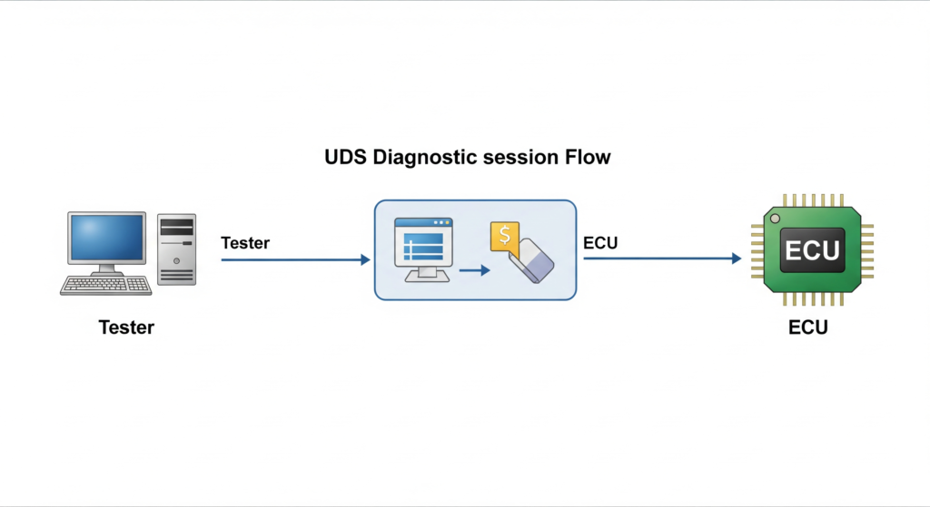
UDS (Unified Diagnostic Services, ISO 14229) is the diagnostic protocol that OEMs and their authorized tools use to communicate with ECUs. While OBD-II is limited to emissions data, UDS provides full access to ECU functionality: reading and clearing fault codes, flashing firmware, adjusting calibration parameters, and unlocking security-protected functions.
Understanding UDS is critical for CAN bus reverse engineering because many advanced operations require sending specific UDS requests over the CAN bus. Key UDS services include:
- 0x10 DiagnosticSessionControl: Switch the ECU between default, extended, and programming sessions.
- 0x22 ReadDataByIdentifier: Read specific data values from the ECU using DID (Data Identifier) codes.
- 0x27 SecurityAccess: Seed-key authentication to unlock protected ECU functions. For a deep dive into reversing these algorithms, see our Seed-to-Key Reverse Engineering guide.
- 0x2E WriteDataByIdentifier: Write configuration or calibration data to the ECU.
- 0x31 RoutineControl: Execute predefined routines like actuator tests or checksum verification.
- 0x34/0x36/0x37 RequestDownload/TransferData/RequestTransferExit: The firmware flashing sequence used to upload new software to an ECU.
- 0x19 ReadDTCInformation: Read diagnostic trouble codes and their status.
UDS messages are transported over CAN using the ISO-TP (ISO 15765-2) protocol, which handles segmentation for messages longer than 8 bytes. A single UDS request might span multiple CAN frames, and protocol analysis tools must reassemble these fragments to decode the complete diagnostic conversation.
Need help with CAN bus analysis or UDS protocol work? Our team has extensive experience with CAN bus reverse engineering across European, Japanese, and American vehicle platforms. Learn about our ECU reverse engineering services.
Hardware Setup for CAN Bus Sniffing
CAN bus reverse engineering starts with the right hardware. You need a CAN interface that connects your computer to the vehicle’s CAN network. The following table compares popular options:
| Tool | Price Range | CAN-FD | Best For |
|---|---|---|---|
| PCAN-USB (Peak) | $250-400 | Yes (Pro model) | Professional use, wide software support |
| Kvaser Leaf Light v2 | $300-500 | Yes | Industrial-grade reliability, API support |
| CANable / CANtact | $25-60 | No | Budget-friendly, open source, SocketCAN |
| ValueCAN (Intrepid) | $500-1200 | Yes | OEM-level analysis, Vehicle Spy support |
| Arduino + MCP2515 | $10-20 | No | Learning and prototyping |
| CSS Electronics CANedge1 | $200-600 | Yes | Standalone logging, SD card recording |
Disclosure: This article contains affiliate links. If you purchase through these links, we may earn a small commission at no extra cost to you. This helps support our content creation.
Physical Connection
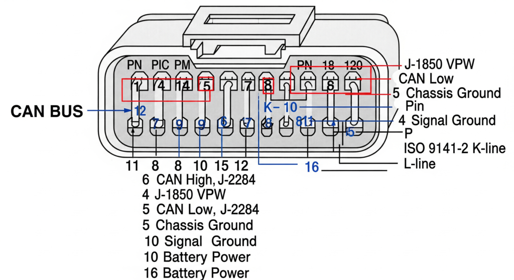
The simplest access point is the OBD-II connector under the dashboard. The standard pinout uses Pin 6 (CAN-H) and Pin 14 (CAN-L) for the high-speed powertrain CAN bus. Connect your CAN interface to these pins, set the correct baud rate (typically 500 kbps for powertrain), and you are ready to capture traffic.
For accessing non-powertrain networks, you may need to tap directly into CAN wiring at specific ECU connectors or junction boxes. This requires a wiring diagram for the target vehicle and careful identification of the correct CAN bus pair.
CAN Bus Reverse Engineering Methodology
With hardware connected and traffic flowing, the real work of CAN bus reverse engineering begins. The methodology follows a systematic approach to decode unknown CAN messages into meaningful signals.
Step 1: Passive Capture and Baseline
Start by recording CAN traffic with the vehicle in a stable state (ignition on, engine running, car stationary). This baseline capture reveals which CAN IDs are active and their typical transmission rates. A modern vehicle generates hundreds of unique CAN IDs, each broadcasting at intervals ranging from 10 ms to 1000 ms.
Step 2: Stimulus-Response Isolation
The core technique in CAN bus reverse engineering is correlating physical actions with data changes. Turn the steering wheel and watch which CAN IDs change. Press the brake pedal and observe which bytes shift. Open a door and note the message that appears. By systematically performing one action at a time while recording, you can map physical events to specific CAN messages and byte positions.
Step 3: Signal Extraction and Scaling
Once you identify which CAN ID and byte(s) carry a signal, the next step is determining the encoding:
- Byte order: Big-endian (Motorola) or little-endian (Intel). Most European vehicles use big-endian, while some Asian and American platforms use little-endian.
- Data type: Unsigned integer, signed integer, or floating point.
- Scaling factor and offset: The raw value is typically scaled. For example, engine RPM might be transmitted as raw_value * 0.25, meaning a raw value of 3200 represents 800 RPM.
- Bit position and length: Signals are not always byte-aligned. A 12-bit signal might start at bit 4 of byte 2 and extend into byte 3.
Step 4: DBC File Creation
As you decode signals, document them in a DBC (Database CAN) file. This industry-standard format stores message definitions, signal names, scaling factors, and value descriptions. Tools like SavvyCAN, Vector CANdb++, and BUSMASTER can import and export DBC files, making your reverse engineering results reusable and shareable.
Step 5: Validation and Cross-Reference
Validate your decoded signals against known reference data. Compare CAN-derived engine RPM with OBD-II PID 0x0C readings. Check decoded vehicle speed against GPS data. Cross-reference coolant temperature with an OBD-II scanner. This validation step catches encoding errors and confirms your CAN bus reverse engineering results are accurate.
Complex CAN bus project? Decoding proprietary CAN protocols, developing custom diagnostic tools, or performing security assessments on vehicle networks requires deep expertise. Contact our team for professional CAN bus reverse engineering support.
Software Tools for CAN Bus Analysis
The right software transforms raw CAN data into actionable intelligence. Here are the essential tools used in professional CAN bus reverse engineering:
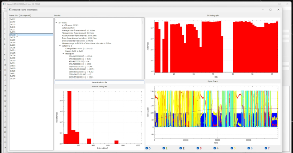
SavvyCAN (Free, Open Source): The go-to tool for CAN bus reverse engineering on a budget. Supports real-time capture, playback, DBC file editing, graphing, and frame comparison. Works with SocketCAN interfaces on Linux and serial CAN adapters on Windows.
Vehicle Spy (Intrepid Control Systems): Professional-grade tool used by OEMs and Tier-1 suppliers. Supports CAN, CAN-FD, LIN, FlexRay, and Ethernet. Includes scripting, automated testing, and advanced signal decoding. Expensive but unmatched in capability.
BUSMASTER (Free, Open Source): Feature-rich CAN analysis tool with J1939 and ISO-TP support. Good for UDS diagnostic development and signal database management.
Wireshark + SocketCAN: On Linux, the SocketCAN framework provides kernel-level CAN support, and Wireshark can capture and dissect CAN frames alongside regular network traffic. Useful for researchers who want protocol analysis in a familiar interface.
can-utils (Linux): Command-line utilities (candump, cansend, cangen, cansniffer) that provide fast, scriptable CAN interaction. The cansniffer tool is particularly useful for CAN bus reverse engineering because it highlights changing bytes in real-time, making stimulus-response analysis efficient.
CANalyze / CANToolz: Python-based frameworks for automated analysis, fuzzing, and custom protocol development. Ideal for security researchers who need scriptable, repeatable test workflows.
CAN Bus Security: Vulnerabilities and Attack Surfaces
CAN bus was designed in the 1980s for reliability, not security. It has no built-in authentication, encryption, or access control. Any node on the bus can send any message with any arbitration ID. This fundamental design choice creates significant security implications that CAN bus reverse engineering reveals.
Known Vulnerabilities
Message spoofing: An attacker with physical CAN access can inject arbitrary messages. If the arbitration ID for “unlock doors” or “disable ABS” is known (through reverse engineering), those commands can be sent from any connected device.
Replay attacks: Captured CAN traffic can be replayed to reproduce actions. Record the CAN sequence for “remote start” and play it back later to start the vehicle without the key.
Bus-off attacks: By deliberately causing CAN error frames, an attacker can force a targeted ECU into bus-off state, effectively disabling it. This could silence the ABS controller or engine management system.
Diagnostic abuse: UDS services like SecurityAccess (0x27) and firmware flashing (0x34-0x37) can be exploited if the seed-key algorithm is weak or the security implementation has flaws. Combined with reverse engineering of the diagnostic flow, an attacker could flash malicious firmware to an ECU.
Defensive Measures
The automotive industry is responding with SecOC (Secure Onboard Communication) as defined in AUTOSAR, which adds message authentication codes (MACs) to CAN frames. CAN-FD’s larger payload makes room for these authentication fields. Newer vehicles also implement gateway ECUs that filter traffic between CAN domains, preventing messages from the infotainment network from reaching the powertrain CAN bus. Understanding these defenses is an important part of modern automotive network security analysis.
CAN Bus Reverse Engineering in Practice: Real-World Applications
The skills and techniques covered in this guide have direct applications across multiple domains:
ECU development and calibration: Performance tuners use CAN bus reverse engineering to identify calibration-related messages, monitor real-time sensor data during dyno runs, and validate ECU modifications. Understanding CAN communication is essential when working with platforms like the Bosch MED17 and EDC17, where CAN messages carry critical engine parameters.
Custom dashboard and data logging: Building aftermarket digital dashboards or data acquisition systems requires decoding CAN signals for RPM, speed, temperatures, pressures, and gear position. CAN bus reverse engineering provides the signal definitions needed to display or record this data.
Automotive security assessment: Penetration testers use CAN bus reverse engineering to evaluate vehicle network security, identify attack surfaces, and recommend mitigations. This work directly supports the growing field of automotive cybersecurity compliance under standards like ISO/SAE 21434 and UNECE WP.29.
Diagnostics tool development: Independent diagnostic tool manufacturers reverse engineer OEM CAN protocols to provide dealer-level functionality in aftermarket tools. This requires decoding both the raw CAN layer and the UDS diagnostic layer.
Immobilizer and security system analysis: CAN bus carries the communication between the immobilizer module and engine ECU. Analyzing these messages is often the first step in ECU immobilizer reverse engineering and ISN recovery projects.
Firmware extraction support: Before extracting ECU firmware, CAN bus analysis helps identify the correct UDS session, security access sequence, and download protocol parameters. This preparation work directly feeds into the ECU firmware extraction process.
From CAN Data to ECU Firmware: The Complete Pipeline
CAN bus reverse engineering rarely exists in isolation. It is typically one stage in a larger ECU analysis pipeline:
- CAN bus sniffing and message identification to understand the target ECU’s communication behavior and diagnostic protocol.
- UDS session establishment and SecurityAccess bypass to unlock protected ECU functions.
- Firmware extraction via the CAN-based flashing protocol (UDS 0x34/0x36/0x37) or through physical methods like JTAG and boot mode.
- Static firmware analysis using disassemblers like Ghidra or IDA Pro to understand the ECU’s internal logic. Our Advanced ECU Firmware Reverse Engineering Methodology covers this phase.
- Calibration modification and checksum correction to apply changes while maintaining firmware integrity. See our ECU Checksum and CRC Algorithms guide for this step.
- Re-flashing and validation using the CAN-based UDS protocol to upload modified firmware and verify correct operation.
This pipeline demonstrates why CAN bus reverse engineering is a foundational skill. Every subsequent step depends on the CAN-level understanding established in the first phase.
Conclusion
CAN bus reverse engineering opens the door to understanding how vehicles truly communicate at the electronic level. From decoding simple sensor values to analyzing complex diagnostic protocols, the ability to read and interpret CAN traffic is fundamental to ECU development, automotive security research, and advanced vehicle diagnostics.
The key principles to remember: always start with passive observation before active interaction, use systematic stimulus-response testing to isolate signals, document everything in DBC format for reproducibility, and validate your findings against known reference data. The CAN protocol itself is simple, but the volume of proprietary messages and manufacturer-specific encodings make each vehicle a unique puzzle.
As vehicles evolve toward CAN-FD, Automotive Ethernet, and SecOC-protected communications, the fundamentals of CAN bus reverse engineering remain relevant. The methodology adapts to new transport layers, but the core approach of capture, correlate, decode, and validate stays the same. Master these fundamentals, and you will have the skills to tackle any vehicle network analysis challenge.
Let's Work Together
Need Professional Assistance with Reverse Engineering or Cybersecurity Solutions? Our Team is Ready To Help You Tackle Complex Technical Challenges.