
Calibration extraction, the reliable identification, extraction and validation of calibration tables from ECU firmware is a high-value technical capability required by tuners, OEM engineers, workshops and forensic practitioners. Done correctly it unlocks controllable, auditable changes to fueling, ignition, torque management and a host of engine control parameters; done poorly it risks mis-tuning, regulatory breach or irrecoverable hardware damage. This article explains the disciplined, tool-independent engineering approach we use to find maps, infer their axes and verify them safely in bench and vehicle settings
What calibration maps control and why extraction matters
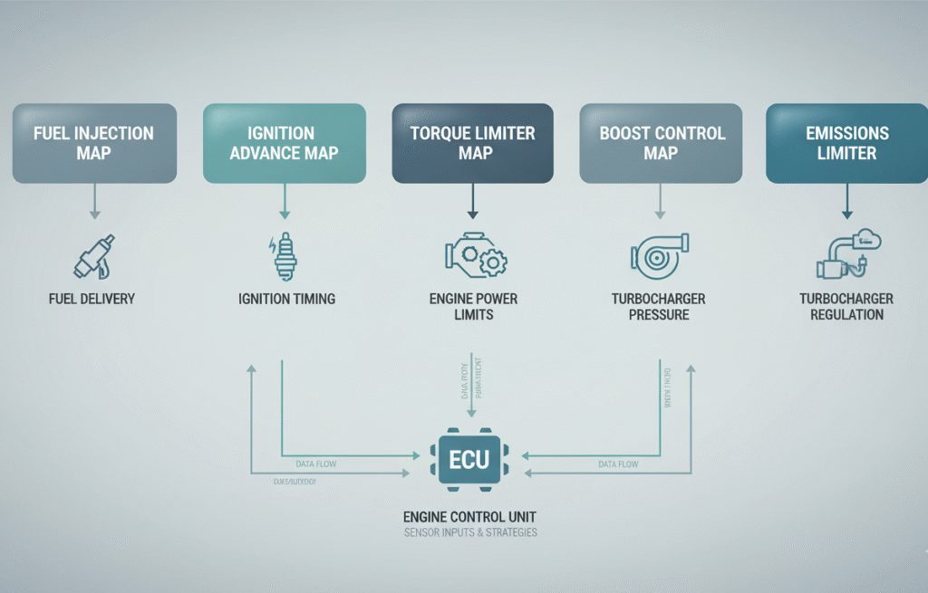
Calibration maps embody the numerical logic that translates sensor and operator inputs into commanded outputs: fuel injector pulse widths, ignition timing advance, torque limits, boost control scalars and limp-home thresholds are defined as numerical maps. The practical implications are simple: To modify performance, emissions or drivability you usually need to alter one or more maps in a controlled manner. For forensic work, the reverse is true, extracting maps and associated logs can provide an evidentiary view of how a vehicle behaved and why.
Because calibration data frequently interacts with safety and emissions systems, extraction workflows must mandate proof of authorization and a defensible evidence trail before any intrusive work begins. Best practice is to record acquisition metadata (who authorized the work, which physical unit was used, the exact extraction method, and cryptographic hashes of acquired images) so that every downstream artifact can be traced back to an auditable original. The procedural framing of this acquisition and logging stage aligns with accepted digital forensics guidance.
Memory layout patterns and common map signatures
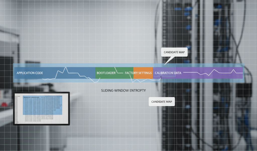
Maps are typically stored as contiguous regions of numeric values with predictable alignment and cell spacing. Typical patterns include sequences of regularly spaced values, monotonic progression across an axis, and low local entropy compared with compressed code blocks. Table shapes are often 1D, 2D or 3D matrices with integer or fixed-point entries; axis scales commonly follow OEM conventions (RPM, load, temperature, manifold pressure, pedal position). Recognizing these patterns is the first filter used to separate promising data regions from code, strings or binary resources.
In practice, experienced engineers combine visual inspection of hex dumps with compact statistical metrics to highlight candidates. For example, a contiguous region that exhibits regular step sizes in value, low byte-variance and clear alignment boundaries is a natural candidate for further inspection. Industry training and map-identification courses emphasize pattern recognition and scaling heuristics as an essential skill set for reliable extraction. High Performance Academy
Heuristics and algorithmic detection methods
To reduce manual guesswork we formalize heuristics into small, repeatable tests. Sliding-window entropy profiling is a robust, general-purpose method: by computing entropy across overlapping windows and plotting the result you can visually separate low-entropy calibration regions from higher-entropy code or compressed blobs. The sliding-window technique is a common signal processing method that has shown reliable utility in automotive and in-vehicle network analyses.
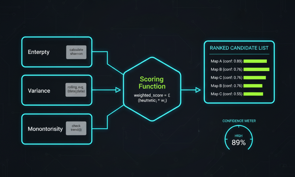
Other complementary statistical checks include inter-cell variance (maps tend to have lower variance within local neighborhoods), monotonicity checks (many axis sequences are monotonic), and repeated-pattern detection (tables frequently include repeated row/column structures). Combining multiple metrics into a scoring function entropy, variance, monotonicity score produces a ranked list of candidate regions that materially speeds manual verification.
Axis inference; Turning a Candidate Table Into Usable Calibration
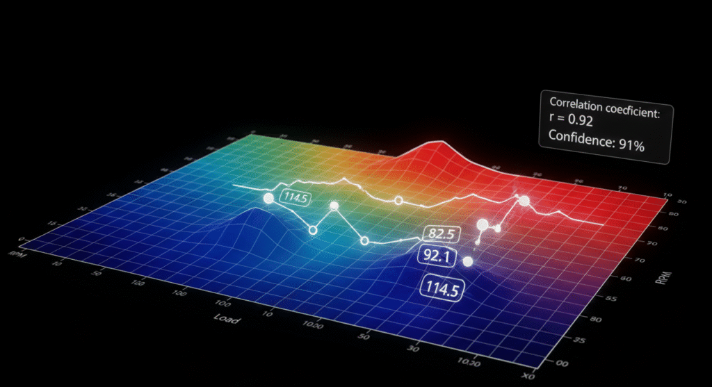
A region of data becomes a usable calibration only when its axes are correctly identified (e.g., which dimension corresponds to RPM, which to load, and what numeric scale is used). Axis inference is best treated as an empirical correlation problem. Capture synchronized telemetry, ideally, multiple runs of controlled inputs and compute correlation metrics between telemetry channels (RPM, MAP, TPS, vehicle speed) and time-aligned samples from candidate memory offsets. High Pearson correlation or consistent cross-correlation lags indicate strong axis candidates.
In more sophisticated environments this correlation approach is augmented by machine-learning and statistical signal analysis applied to OBD/telemetry datasets; academic and industry work shows that telemetry-driven inference and ML-assisted feature extraction can reliably classify signal relationships when datasets are clean and well-synchronized. Use correlation results to produce per-axis confidence scores rather than binary labels confidence metrics support conservative downstream decisions during patching and validation.
Practical workflow and verification (tool-independent)
A pragmatic, repeatable workflow looks like this (high level):
- Acquire and validate a bit-for-bit image with full metadata and cryptographic hashes. Maintain a chain-of-custody ledger.
- Profile the image with entropy and pattern detectors to produce candidate regions. Use windowed entropy + variance + monotonicity scoring to rank candidates.
- Export candidates into a human-readable grid view for visual inspection (CSV or matrix view). Treat this as hypothesis generation rather than final truth.
- Collect synchronized telemetry under controlled inputs and compute correlation metrics between telemetry signals and candidate cells. Rank axis hypotheses by confidence.
- Validate on bench using sensor simulation and limited dynamic inputs before any vehicle deployment; maintain rollback images and strict flash SOPs.
- Deliver verified artifacts (hashed original image, exported calibration CSV/XDF, axis confidence report, and a validation checklist).
This workflow is intentionally tool-agnostic: calibrated exports should be portable (CSV/XDF) so clients can consume them with their chosen calibration viewers or analysis suites. Industry training materials and manuals for common calibration editors underscore the same high-level process detect, inspect, correlate, validate while differing mainly in UI and automation support.
Verifying extracted maps safely
Validation is a non-negotiable part of calibration extraction. Bench validation uses sensor simulators to sweep input ranges (RPM, MAP, throttle) and observe outputs while capturing CAN/UDS traces and logging timestamps. Compare before/after traces and compute regression metrics: does the patched or interpreted map produce expected actuator responses without triggering DTCs or safety limits? Establish pass/fail thresholds in advance and record every test run. Forensic or OEM contexts demand that these verification artifacts be preserved and shipped with the deliverable.
If on-vehicle testing is required, proceed only after bench validation and with documented safety controls: experienced test personnel, clear risk acceptability criteria, and telemetry logging that can be compared to bench results. Provide rollback images and documented SOPs in the delivery package.
Common pitfalls and troubleshooting
The most common failure modes in projects follow distinct patterns: incorrectly defined axes (e.g., RPM and load values being swapped), false-positive results due to structured but non-calibrated data, compressed or encrypted partitions, and signed firmware regions that cannot be reflashed without an authorized key. Such problems can delay a company’s ECU firmware reverse engineering process or lead to incorrect results; therefore, early detection and documentation are essential. An effective error-detection approach involves cross-validating axis inference hypotheses across multiple conditions, comparing them with different telemetry sets, and measuring confidence by testing the same candidate region on different runs.
Furthermore, human verification (visual inspection and statistical checks) should be mandated in calibration extraction steps rather than automated scoring. Especially for calibration map extraction claims, statistical scores alone should not be sufficient; each candidate should be manually checked. When protected or signed partitions are detected, document this immediately in the feasibility report. This allows the customer to evaluate realistic options, such as re-signing, OEM approval, or hardware replacement, at an early stage. This precautionary approach both increases the reliability of the ECU firmware analysis process and makes risks predictable.
Deliverables and Client Handoff
The delivery package of a professional calibration extraction service consists not only of technical deliverables but also of management documentation that ensures auditability and traceability. A typical delivery includes: the hashed original image (SHA-256/MD5), the candidate address map and ranked confidence scores for each region/axis, exported CSV/XDF files resulting from the calibration map extraction, synchronized CAN/UDS telemetry logs, bench verification reports, and a short feasibility memo (protected or signed partition information, missing key notes) to be shared with the customer.
This structure not only meets the needs of the OEM or workshop; It also provides the traceability necessary for forensic investigation: when address maps, axis inference scores, and bench test results are combined, an expert third party can re-verify the work. Upon delivery, all files should be under version control and provided with immutable hash metadata. Furthermore, flashing SOPs and rollback images should be provided to the client, allowing for quick reversals to the original state when necessary. This preserves the integrity of the calibration extraction process and minimizes operational risk for the client.
Conclusion and Best Practices Summary

Reliable calibration extraction is a combination of pattern recognition, statistical inference, and controlled verification. An effective process uses statistical heuristics such as sliding-window entropy, variance/monotonicity, and other factors to identify candidate regions, apply comprehensive telemetry correlations for axis inference, and test all hypotheses against defined pass/fail criteria on the bench. Additionally, a full chain of custody and versioned deliverables must be ensured at every stage: this ensures that the outputs of ECU firmware reverse engineering and ECU firmware analysis are acceptable to the OEM, legal authorities, or auditors.
If you’re looking for an experienced team for these projects, ReverseEngineer.net can help. Our expert engineers handle calibration extraction, calibration map extraction, axis inference, and comprehensive ECU firmware reverse engineering projects with forensic-level documentation. We work with reference-based feasibility studies, hashed sample deliverables, and secure ingestion procedures; Contact us for these projects and schedule a direct consultation with our team. Our certified engineers will quickly provide a feasibility memo and project plan upon receiving your requirements.
Let's Work Together
Need Professional Assistance with Reverse Engineering or Cybersecurity Solutions? Our Team is Ready To Help You Tackle Complex Technical Challenges.