What Is ECU PCB Reverse Engineering?
ECU PCB reverse engineering is the process of analyzing an electronic control unit’s physical circuit board to understand its design, identify components, trace signal paths, and ultimately reconstruct the schematic. While firmware analysis reveals what the ECU software does, PCB reverse engineering reveals what the ECU hardware can do. It exposes the processor, memory chips, communication interfaces, power supply architecture, and sensor input circuits that define the ECU’s physical capabilities.
This discipline is essential for understanding protection mechanisms that exist at the hardware level, identifying debug and programming interfaces hidden on the board, developing custom hardware tools for ECU interaction, and repairing damaged units where replacement is impossible or prohibitively expensive. ECU PCB reverse engineering bridges the gap between firmware analysis and physical hardware understanding.
This guide covers the complete ECU PCB reverse engineering workflow: from initial board inspection and component identification to signal tracing, schematic reconstruction, and practical applications in automotive reverse engineering.
Why Reverse Engineer an ECU Circuit Board?
Before investing hours in board analysis, it helps to understand what ECU PCB reverse engineering can accomplish:
- Locate debug interfaces: JTAG, BDM, SWD, and UART test points are often present on the PCB but undocumented. Finding these interfaces provides direct access to the processor for firmware extraction and live debugging.
- Identify security hardware: Hardware security modules (HSM), secure boot chips, and external encryption ICs are visible on the board. Understanding their connections reveals how the security architecture works at the physical level.
- Understand memory architecture: External flash chips, EEPROM ICs, and RAM modules are identifiable by their part numbers. This tells you the total memory available, the bus width, and potential read/write methods independent of the main processor.
- Develop custom tools: Building bench-mode adapters, boot-mode activation circuits, or custom programming jigs requires detailed knowledge of the PCB layout and connector pinouts.
- Repair and modification: Component-level repair of water-damaged or failed ECUs requires schematic knowledge. Modifications like adding external memory access points or bypassing security components also depend on PCB understanding.
Essential Tools for ECU PCB Reverse Engineering
ECU PCB reverse engineering requires a combination of optical, electronic, and software tools:
| Tool | Purpose | Budget Option | Professional Option |
|---|---|---|---|
| Digital microscope | Component identification, trace inspection | USB microscope ($30-80) | Stereo microscope ($500-2000) |
| Multimeter | Continuity testing, voltage measurement | Fluke 101 ($50) | Fluke 87V ($400) |
| Logic analyzer | Digital signal capture (SPI, I2C, CAN) | Saleae Logic 8 clone ($15) | Saleae Logic Pro 16 ($1500) |
| Oscilloscope | Analog signal analysis, timing | Rigol DS1054Z ($350) | Keysight DSOX3024T ($5000) |
| EDA software | Schematic capture, PCB layout | KiCad (free) | Altium Designer ($7000/yr) |
| Hot air station | Component removal for inspection | Quick 957DW+ ($80) | Hakko FR-810B ($800) |
Disclosure: This article contains affiliate links. If you purchase through these links, we may earn a small commission at no extra cost to you. This helps support our content creation.
Step 1: Initial Board Inspection and Photography
Every ECU PCB reverse engineering project begins with careful visual inspection. Remove the ECU from its enclosure and photograph both sides of the board under good lighting. High-resolution photos serve as your reference throughout the project and allow you to study the board without physically handling it repeatedly.
What to look for initially:
- Main processor: The largest IC on the board, usually centrally located. Read the part number printed on the package (e.g., “SAK-TC1797-512F180E” for a TriCore, “R7F701202” for a Renesas RH850).
- Memory ICs: Flash memory chips (Spansion, Micron, Winbond) and EEPROM ICs (Microchip 93Cxx, ST M95xxx) are typically located near the processor. Their part numbers reveal capacity and interface type.
- Communication transceivers: CAN transceivers (NXP TJA1050/TJA1040, Infineon TLE6250), LIN transceivers, and K-line drivers sit near the board edge connectors.
- Power supply section: Voltage regulators, inductors, and large capacitors form the power supply area, usually near the main connector input.
- Test points and unpopulated pads: These often indicate debug interfaces (JTAG/BDM), manufacturing test access, or programming headers that were used during production but left unconnected in the final product.
Step 2: Component Identification and Datasheets
After photographing the board, create a component inventory. For every IC, read the part number and find its datasheet. This is one of the most valuable steps in ECU PCB reverse engineering because datasheets reveal:
- Pin functions: Every pin on the IC is documented with its purpose (power, ground, data, clock, chip select, etc.).
- Communication interfaces: Which protocols the chip supports (SPI, I2C, parallel, CAN).
- Operating voltages: Power supply requirements and I/O voltage levels.
- Memory maps: For processors, the datasheet provides the internal memory map needed for firmware analysis in tools like Ghidra.
For Bosch ECUs, the main processor datasheet (Infineon TriCore TC1797, TC277, TC298) is publicly available from Infineon’s website. For Bosch MED17 and EDC17 units, this datasheet is the single most important reference document. Similarly, Denso and Continental ECUs use Renesas and Infineon processors with publicly available documentation.
Step 3: Signal Tracing and Connectivity Mapping
With components identified and datasheets in hand, the next step is tracing how everything connects. This is the core skill of ECU PCB reverse engineering.
Continuity Testing
Use a multimeter in continuity mode to trace connections between IC pins. Start with known pins from the datasheet: processor CAN_TX should connect to the CAN transceiver TXD pin, SPI_CLK should connect to the external flash CLK pin, and so on. Systematically work through each processor pin, recording every connection.
Multi-Layer Board Challenges
Automotive ECU boards are typically 4 to 6 layers, meaning many traces run on internal layers invisible from the surface. When continuity testing shows a connection between two points but you cannot see a visible trace, the signal routes through an internal layer. Mark these connections in your notes and verify them with additional continuity checks from intermediate via points.
Power Rail Mapping
Trace the power supply architecture early. Identify the main input voltage (typically 12V from the vehicle battery), the voltage regulators that generate 5V, 3.3V, and 1.2V rails, and which components connect to each rail. This mapping is essential for understanding the board’s power domains and for safely powering the ECU on the bench during testing.
Step 4: Debug Interface Identification
One of the highest-value outcomes of ECU PCB reverse engineering is finding debug and programming interfaces. These interfaces provide direct access to the processor, bypassing all software-level security.
| Interface | Signals | Typical ECU Usage | What to Look For on PCB |
|---|---|---|---|
| JTAG | TCK, TMS, TDI, TDO, TRST | TriCore, ARM-based ECUs | 5-pin header, test pads near processor |
| BDM | BKPT, DSCLK, DSI, DSO | Freescale/NXP PowerPC ECUs | 4-6 pin header or pads |
| SWD | SWDIO, SWCLK | ARM Cortex-M based ECUs | 2-pin test pads near processor |
| AUD (Renesas) | AUDCK, AUDATA[0:3] | Denso (SuperH, RH850) | 6-8 pin header or pads |
| UART/Serial | TX, RX, GND | Boot mode, debug console | 3 pads in a row, often near processor |
To find these interfaces, look for groups of test pads or unpopulated headers near the main processor. Trace each pad back to the processor using continuity testing, then match the connected processor pins against the datasheet’s debug interface pinout. When a group of pads matches a known debug interface, you have found your access point.
Need help identifying debug interfaces on an ECU board? Our team has mapped hundreds of ECU PCBs across Bosch, Denso, and Continental platforms. Learn about our ECU reverse engineering services.
Step 5: External Memory Chip Analysis
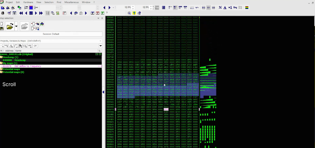
External flash and EEPROM chips are high-value targets in ECU PCB reverse engineering. These chips often store calibration data, immobilizer keys, adaptation values, and sometimes portions of the main firmware that can be read independently of the main processor.
Common external memory types in ECUs:
- SPI Flash (Winbond W25Q, Micron M25P): Connected via 4-wire SPI bus. Can be read in-circuit using a SOIC-8 clip or desoldered and read with a universal programmer.
- EEPROM (Microchip 93Cxx, ST M95xxx): Stores configuration data, VIN, immobilizer secrets, and mileage information. Small capacity (256 bytes to 64 KB) but critical data. For details on immobilizer data stored in these chips, see our ECU Immobilizer and ISN Recovery guide.
- Parallel NOR Flash (Spansion S29GL, Micron M29W): Used in older ECUs for main firmware storage. Requires parallel bus access or BDM/JTAG through the processor.
Reading external memory chips provides an alternative firmware extraction path when the main processor’s debug interface is locked or disabled. It also reveals data that the processor stores externally for persistence across power cycles.
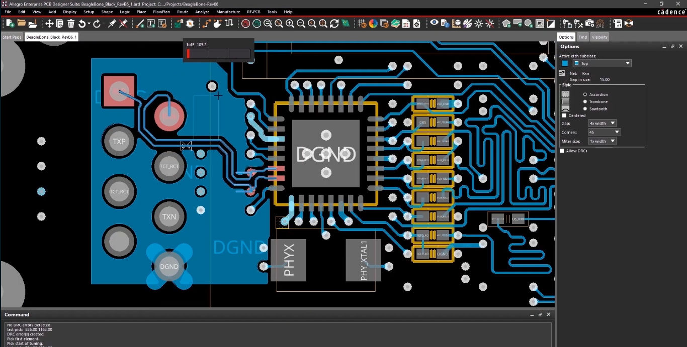
Step 6: Schematic Reconstruction
The final phase of ECU PCB reverse engineering is assembling all findings into a schematic diagram. Using EDA software like KiCad (free) or Altium Designer, create a schematic that documents every component, connection, and signal path on the board.
Organize the schematic by functional blocks:
- Power supply: Battery input, reverse polarity protection, voltage regulators, power sequencing.
- Processor core: Main MCU with all pin connections, clock crystal, reset circuit.
- Memory: External flash, EEPROM, RAM with their bus connections.
- Communication: CAN transceivers, LIN drivers, K-line interface, Ethernet PHY (newer ECUs).
- Sensor inputs: ADC channels for temperature, pressure, position sensors. Conditioning circuits (voltage dividers, filters, protection diodes).
- Actuator outputs: Injector drivers, ignition coil drivers, relay controls, H-bridge motor drivers.
- Debug/programming: JTAG/BDM/SWD interface, boot mode selection circuit.
A complete schematic is invaluable for future work on the same ECU family. It serves as the reference document for developing custom tools, understanding CAN bus communication paths, and planning firmware extraction strategies.
Complex ECU hardware analysis project? From multi-layer PCB tracing to complete schematic reconstruction, our team delivers detailed hardware documentation for any ECU platform. Contact us to discuss your project.
Practical Applications and Real-World Examples
Boot mode activation circuits: Many processors have dedicated pins that select the boot mode during power-up. ECU PCB reverse engineering reveals which pins control boot mode selection and how to activate it by pulling specific lines high or low. This knowledge is critical for firmware extraction via boot mode.
Security chip bypass: Some ECUs include external security ICs (e.g., Infineon SLB9670 TPM, Maxim DS28E01 secure authentication) that validate firmware or protect cryptographic keys. Identifying these chips through PCB analysis reveals whether the security is implemented externally (potentially bypassable by isolating the chip) or internally within the main processor.
Fault diagnosis and repair: When an ECU fails, PCB knowledge allows component-level diagnosis. Blown MOSFETs in injector drivers, failed voltage regulators, or damaged CAN transceivers can be identified and replaced when you have a schematic reference.
Clone and counterfeit detection: Comparing a suspected counterfeit ECU board against known genuine boards reveals differences in component quality, PCB layer count, and manufacturing standards. This application is growing in importance as the automotive aftermarket faces increasing counterfeit electronic parts.
Tips for Efficient ECU PCB Reverse Engineering
Start with the processor datasheet. The processor pinout is your roadmap. Every trace on the board connects to a known processor function. Work outward from the processor to each connected component.
Photograph everything before touching. High-resolution photos of both board sides, macro shots of IC markings, and overview shots showing component placement save time and prevent mistakes. Some IC markings fade or become unreadable after handling.
Use colored markers on photos. Overlay your trace findings on board photos using different colors for power, ground, data, and clock signals. This visual mapping helps you see the overall architecture at a glance.
Check for known ECU pinouts. Before starting a full PCB reverse engineering effort, search for existing documentation. Many popular ECU models have community-documented connector pinouts and partial schematics that give you a head start.
Cross-reference with firmware analysis. If you have already analyzed the firmware using advanced reverse engineering methodology, the code reveals which peripherals are initialized, which GPIO pins are configured as inputs or outputs, and which communication protocols are active. This firmware knowledge guides your physical tracing efforts.
ReverseEngineer.net
ECU PCB reverse engineering is the hardware foundation that supports all other ECU analysis work. Understanding the physical board reveals debug interfaces for firmware extraction, memory chips for data recovery, security hardware for vulnerability assessment, and circuit designs for custom tool development. While firmware analysis tells you what the ECU software does, PCB reverse engineering tells you what the hardware makes possible.
The skills involved, from reading datasheets and tracing signals to reconstructing schematics, are fundamental electrical engineering competencies applied to the specific domain of automotive electronics. Master these skills, and you gain the ability to approach any ECU, regardless of manufacturer or generation, with confidence in understanding its hardware architecture from the board level up.
Let's Work Together
Need Professional Assistance with Reverse Engineering or Cybersecurity Solutions? Our Team is Ready To Help You Tackle Complex Technical Challenges.