
This article presents a real-world approach to PowerPC ECU reverse engineering, covering physical analysis, firmware dumping, and decoding automotive logic.
Modern vehicles rely on dozens of Electronic Control Units (ECUs) to manage everything from engine performance to safety systems. Many of these ECUs are built around PowerPC-based microcontrollers – notably NXP/Freescale’s MPC55xx series – which were widely used in automotive applications for their performance and reliability. This guide will walk through a practical case-study approach to reverse engineering a PowerPC-based ECU, from initial hardware inspection to firmware analysis. We’ll cover how to access the ECU’s firmware, common challenges (like locked debug interfaces and protected memory), basics of analyzing the code, and real-world applications such as diagnostics, cloning, and customization.
Understanding PowerPC-Based ECUs
An automotive ECU is essentially an embedded computer dedicated to a specific function in the vehicle (engine control, transmission, ABS, etc.). PowerPC-based ECUs are those using microcontrollers from the PowerPC/Power Architecture family. During the 2000s and 2010s, PowerPC MCUs (like the Freescale MPC5500/5600 series) were a popular choice for engine and powertrain controllers due to their 32-bit performance, robust peripheral set (CAN bus, ADCs, timers, etc.), and automotive-grade reliability. These chips often feature substantial on-chip flash memory (e.g. 1–2 MB) and RAM, running the manufacturer’s proprietary firmware. In practical terms, a PowerPC-based ECU is responsible for real-time control algorithms and diagnostic functions. Reverse engineering such an ECU gives us insight into how these algorithms work and how the ECU communicates (for instance, decoding how it triggers diagnostic trouble codes or handles immobilizer keys). Understanding the architecture (PowerPC is a RISC architecture, usually big-endian, sometimes with Variable Length Encoding (VLE) for compact code) is important when setting up tools to analyze the firmware. Overall, recognizing that an ECU’s brain is a PowerPC MCU helps target the correct tools and methods for exploration.
Reverse Engineering Process: From Physical Inspection to Firmware Dump
Tackling an ECU reverse engineering project begins with systematic hardware analysis and ends with obtaining the firmware binary. Here’s a structured approach from physical inspection to reading the firmware:
- Initial Inspection – Identify the Hardware: Begin by opening the ECU’s enclosure (often a metal case) to access the circuit board. Observe the PCB and identify key components: the central microcontroller (usually the largest chip, often an NXP/Freescale part number), any memory chips (flash or EEPROM), and connectors. Look for large multi-pin connectors used in the vehicle harness (for power and data like CAN bus), and check for any smaller, unpopulated headers or test pads. These unpopulated pads may hide debug interfaces like JTAG – waiting to “spill their secrets if probed correctly”. For example, an ECU board might have test pins aligned in a row corresponding to the MCU’s JTAG port. Identifying silkscreen labels or chip markings at this stage is crucial.
- Gather Documentation (Datasheets & Schematics): Once you’ve identified the MCU and any external memory, obtain their datasheets or reference manuals. The MCU’s documentation will reveal its architecture, memory map, pinouts, and the location of any debug or programming interfaces. For instance, the NXP MPC55xx reference manual will confirm the presence of a JTAG (IEEE 1149.1) interface and tell you which pins on the chip are TCK, TMS, TDI, TDO (the JTAG signals). Similarly, if there’s an external flash chip, its datasheet will explain how to read it in-circuit or via a programmer. Having the chip documentation guides your strategy – whether you can read the flash through the MCU or need to access an external chip directly. In some cases, the manufacturer’s datasheet may even mention a special “boot mode” that allows reading or writing memory via a serial interface.
- Locate the Debug/Programming Interface: With knowledge from the documentation, identify where on the ECU board you can tap into the MCU’s debug interface. Many automotive PowerPC MCUs use a JTAG port (or a compatible Nexus debug port) for development and programming. Trace the board for any pin header that connects to the MCU’s JTAG pins (sometimes the pads are arranged in a standard 14 or 20-pin JTAG layout). If no header is present, you may need to solder fine wires to test pads or directly to the chip’s pins for TCK, TMS, etc. This step often requires patience and good magnification, especially if the board has conformal coating or epoxy potting (which some ECUs use to protect components). Be mindful of not shorting anything and consider using a multimeter to confirm continuity between suspected pads and the MCU pins.
- Connect a Debug Tool: Once the interface is accessible, connect an appropriate hardware tool to communicate with the ECU. Options include a JTAG/SWD probe or an ECU bench programmer that supports the specific MCU. Common tools for PowerPC-based MCUs range from professional debuggers (Lauterbach TRACE32, NXP CodeWarrior TAP, P&E Micro, etc.) to lower-cost or open-source options (some hobbyists use BDM debuggers or DIY interfaces for older Freescale chips). Ensure that the ECU is powered safely on the bench with a stable power supply at the correct voltage (most run on 12V input with on-board regulators, but you may need to provide 5V or 3.3V to certain pins according to the ECU pinout). The debug probe typically connects to a PC running software that can halt the processor and access memory. If the MCU supports a boot ROM mode, an alternative is to put the ECU into that mode (often by pulling a certain pin high or low during reset) and use a vendor tool or script to read flash content via CAN or UART.
- Dump the Firmware: Using your tool, issue a read command for the MCU’s internal flash memory. Ideally, the debugger halts the CPU, allowing a non-intrusive memory dump. In practice, you might use the MCU’s JTAG interface to download the flash contents or use an API if available. This is where preparation meets potential roadblocks – many automotive MCUs enable security features that prevent easy reading. If you’re lucky and the ECU isn’t security-locked, you’ll obtain a binary image of the firmware. If it is locked (very common in newer ECUs), the debugger might refuse access or report a protection error. In such cases, more advanced techniques come into play: some engineers perform a chip-off (desolder the MCU or flash chip to read it with a programmer), or use glitching and fault injection to temporarily bypass security. Car hacking experts also look for backdoor service modes (for example, OEM diagnostic modes that allow reads) or exploit the bootloader code. It’s worth noting that professional reverse engineering services employ methods like JTAG, BDM, chip-off, and even custom hardware tricks to extract firmware. For our general example, let’s assume the firmware was successfully dumped via JTAG, resulting in a binary file (often a few hundred kilobytes to a few megabytes in size).
Overcoming Common Challenges
Reverse engineering automotive ECUs is rarely straightforward. Here are some common challenges you may need to address:
- Locked Debug Access: Manufacturers often enable security on production ECUs. This can require a secret key (password) to unlock the JTAG or Nexus debug interface. For example, many GM PowerPC-based ECUs (MPC55xx/MPC56xx) use a “shadow password” in flash that must be known before any debugging is allowed, similar to seed-to-key security mechanisms found in diagnostic protocols If you attempt to connect without the correct password, the MCU may refuse access or even wipe the flash as a defense. Overcoming this usually means finding the key (sometimes by reading an external memory that holds it, or by brute-force if feasible, or by exploiting firmware vulnerabilities). In some cases, specialists resort to decapsulating the chip to read out fuse values or use fault injection to bypass the check.
- Protected Flash Memory: Even if you can interface with the ECU, the internal flash may be read-protected. Some MCUs allow a mass erase to remove protection (erasing the firmware in the process, which defeats the purpose if we want the code intact). Others might use encryption or proprietary algorithms to store code. It’s not uncommon to find that the firmware you dumped is compressed or encrypted to make reverse engineering harder. For instance, an ECU’s update file or stored code might use compression (like LZSS or Huffman coding) or encryption (AES/RSA-based secure boot). Reverse engineers must then identify and undo these protections by analyzing the bootloaders or using tools like binwalk (for detecting compressed sections). In one case study, a heavy-truck ECU firmware dump had to be decompressed from a custom format before any meaningful analysis could be done (the decompression algorithm was found by studying the firmware’s initialization routines).
- Toolchain and Compatibility Issues: Working with a less common CPU architecture can introduce compatibility hurdles. PowerPC architecture is different from the typical x86 or ARM that many tools and engineers are used to. You must ensure your disassembler or emulator supports the specific PowerPC variant and its endianness (most automotive PowerPC MCUs are big-endian). Additionally, the MPC55xx series supports Variable Length Encoding (VLE) instructions, which means the code might use 16-bit compact opcodes alongside 32-bit ones. Not all reverse engineering tools handle VLE out-of-the-box you might need to configure settings or use specific processor modules (for example, Ghidra has a language option for PowerPC VLE). If you plan to modify and rebuild code, you’d need a compiler toolchain that supports the PowerPC Book E architecture and VLE (NXP’s CodeWarrior or Wind River Diab compiler, etc.), which can be another challenge as these are specialized (and often expensive) tools. For most, sticking to analysis and patching the binary with assembly is more practical than fully recompiling an ECU firmware.
- Hardware and Electrical Hurdles: On the hardware side, ECUs are designed to be tough – they may have conformal coatings, tamper-resistant screws, or potting material that make just accessing the PCB difficult. You’ll need to carefully remove any protective resin and be cautious not to damage the board. Powering up the ECU on the bench can also be tricky; many ECUs won’t fully operate until certain conditions are met (e.g. ignition line voltage present, or CAN bus activity). It’s often necessary to simulate the car’s environment by providing ignition feed and terminating communication lines properly. Lastly, handling the MCU itself (especially if a chip-off is needed) requires skill in soldering and possibly expensive programming adapters. Always double-check pinouts and work methodically to avoid irreversibly bricking the unit.
Despite these challenges, a methodical approach and the right equipment will eventually lead to a successful firmware extraction. It’s wise to practice on a spare or junkyard ECU before tackling one that is mission-critical.
Analyzing the Firmware Image in PowerPC ECU Reverse Engineering
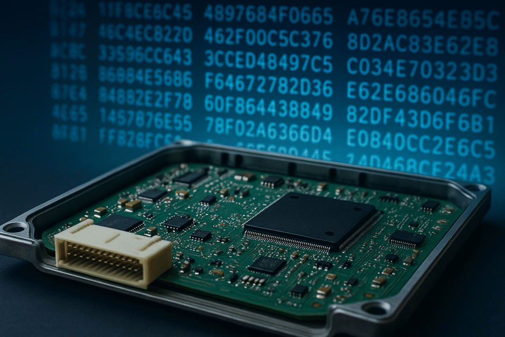
Figure: An open ECU board (foreground) and a representation of extracted firmware data (hexadecimal code in background). With the firmware dump in hand, engineers move on to software analysis.
Once you have the raw firmware binary from the ECU, the focus shifts to software analysis. This step turns the opaque bytes of the dump into meaningful information about how the ECU operates. Here are the basic approaches to analyzing an ECU firmware:
- Load the Firmware into a Disassembler/Decompiler: Tools like Ghidra and IDA Pro are invaluable for this task. Start a new project in your reverse engineering tool and specify the correct processor architecture (for an MPC55xx, you’d choose PowerPC – 32-bit, and enable the VLE extension if applicable). Set the memory map according to the MCU’s address space (the reference manual can tell you, for example, that flash is mapped at address 0x0000_0000 or 0x00F0_0000 depending on the device). Once loaded, the tool will disassemble the machine code into assembly instructions. Initially, it may just show a sea of disassembled instructions with no labels; your job is to make sense of it.
- Identify Firmware Structure: A typical automotive ECU program has an initialization section, a main loop, and multiple interrupt service routines (for engine cycle events, communication, etc.). Using the datasheet and known reset vector address, locate the reset/boot code. Mark the start of code and let the tool auto-analyze from there. You’ll start to see functions being defined. Look for recognizable patterns or constants for example, strings that might contain diagnostic trouble code identifiers or firmware version info (strings in embedded ECUs are sometimes scarce, but you might find a few). If you have access to a map file or debug symbols (perhaps from an update package or similar), that can greatly speed up understanding; however, in pure reverse engineering you often won’t have that luxury.
- Analyze Functions and Logic: Begin examining the disassembled code function by function. High-level tools can translate assembly into pseudo-C code (IDA’s Hex-Rays decompiler or Ghidra’s decompiler) which is extremely helpful to understand logic. Pay attention to how the code reads sensors and writes to actuators (these correspond to memory-mapped I/O registers, whose addresses you can cross-reference in the MCU’s manual). For instance, if you see the code reading from an address like 0xFFF3_0010, and the reference manual says that’s a CAN bus register, you’ve probably located the CAN communication routine. Similarly, timing loops and table lookups likely relate to engine maps or other calibrations. Reverse engineering an ECU often involves identifying these calibration tables (large arrays of data points for fuel, spark, etc.) and checksum and CRC algorithms that validate them. Our tools let us annotate the code – we name functions and variables as we deduce their purpose. Over time, a picture emerges of the ECU’s software architecture.
- Use Emulation and Testing (if possible): In some cases, you can employ emulation or live testing to aid analysis. Emulators like QEMU have support for certain PowerPC cores, which might allow you to execute pieces of the firmware in a sandbox environment. More commonly, if you have a working ECU on the bench, you can perform interactive debugging: for example, using a JTAG debugger to set breakpoints at certain code locations while the ECU runs (this depends on overcoming any security and having a proper debugger). By observing variables and execution flow in real-time, you can confirm hypotheses about what certain code sections do. However, many automotive reverse engineering projects rely primarily on static analysis due to the difficulty of live debugging on locked-down ECUs.
Throughout the analysis, it’s crucial to stay organized keep notes on what each discovered function or variable likely represents. Leverage community knowledge as well: many cars use similar chips and there are forums and databases where enthusiasts have partially documented functions (for instance, open-source ECU projects or prior case studies on similar ECUs). Reverse engineering firmware is an iterative and time-consuming process, but each insight into the assembly code brings you closer to understanding (and potentially modifying) the ECU’s behavior.
Practical Applications of ECU Reverse Engineering
Why go through all this effort? Reverse engineering ECUs has several practical benefits for automotive professionals and enthusiasts. Here are a few important applications:
- Advanced Diagnostics: Knowing the internal firmware logic allows deeper diagnostics than standard tools. For example, by extracting and reading an ECU’s fault code table, one can discover exactly what conditions trigger a certain Diagnostic Trouble Code and even identify undocumented error codes. This can help a technician pinpoint why a vehicle is throwing a specific error or modify thresholds for triggering limp mode, etc. Understanding the code can also reveal hidden self-test routines or data that normal scan tools can’t access, enabling more thorough troubleshooting.
- ECU Cloning and Repair: If you need to replace a damaged ECU, simply swapping it often doesn’t work without proper reprogramming mainly due to immobilizer systems and vehicle-specific calibrations. Reverse engineering lets you clone an ECU by reading the firmware (and data like immobilizer keys) from the original unit and writing it to the new one. Even when official tools block read/write, a direct firmware dump and flash can copy everything, restoring a vehicle to operation. This is especially useful for rare or older vehicles where dealer tools are unavailable. Additionally, by understanding the firmware, one can sometimes repair issues – for instance, patching a known software bug in the ECU code or re-enabling a feature that was disabled, extending the life of hardware that the manufacturer no longer supports.
- Customization and Tuning: Perhaps the most popular motivation for ECU reverse engineering is performance tuning and feature customization. Once the maps and algorithms are understood, an engineer can adjust parameters for more horsepower, better fuel efficiency, or compatibility with aftermarket parts (like bigger fuel injectors or turbochargers). Beyond tuning calibrations, deeper modifications are possible: adding new functionalities or deleting unwanted systems like DPF and EGR. For example, one could disable a hard speed limit, or implement a custom traction control algorithm by injecting new code effectively modding the car’s software. Such advanced modifications require intimate knowledge of the firmware’s workings, which this reverse engineering process provides. In practice, specialized software exists for editing known ECU maps, but with full firmware access you’re not limited to what those tools support. The possibilities range from swapping engines (and making the ECU think it’s running a different configuration) to creating custom diagnostic messages. Manufacturers protect their firmware for exactly this reason but once we peel back the layers, we gain the freedom to innovate.
- (Note: For a breakdown of the most requested modifications, see our guide on the top 6 common ECU modification services)
All of these applications showcase the value of having full insight into an ECU’s software. Whether for legitimate repair and maintenance, or aftermarket creativity, the ability to reverse engineer an ECU opens up opportunities that standard interfaces don’t allow.
Reverse engineering a PowerPC-based automotive ECU is a challenging but rewarding endeavor. By systematically examining the hardware, carefully extracting the firmware, and using powerful software tools to analyze the code, we can demystify the inner workings of these critical vehicle computers. We’ve seen how an ECU based on an NXP MPC55xx series microcontroller can be approached like a case study from identifying a JTAG port to dumping the flash, and then making sense of hundreds of kilobytes of PowerPC assembly. Along the way, we tackled common obstacles like security locks and data encryption, and highlighted practical outcomes like enhanced diagnostics, ECU cloning, and custom tuning.
While the process requires patience and technical skill in both electronics and software, the end result is a deeper understanding of automotive systems and the ability to push beyond factory limitations. It’s the kind of work that bridges the gap between an automotive technician, an electrical engineer, and a software hacker truly interdisciplinary.
The reverseengineer.net team has deep experience in PowerPC ECU reverse engineering and is available to support such projects. Whether you’re looking to unlock an engine controller’s secrets or modify its behavior, our experts can assist in navigating the complexities of the hardware and firmware to achieve your goals. With the right approach and expertise, even the most secure ECU can eventually yield its insights, driving innovation in the automotive world
Let's Work Together
Need Professional Assistance with Reverse Engineering or Cybersecurity Solutions? Our Team is Ready To Help You Tackle Complex Technical Challenges.