
Project Overview: Denso ECU Reverse Engineering That Works
In this case study, we explore how ReverseEngineer.net implemented a firmware patch to retain a driver’s selected performance map on a Denso Diesel ECU across ignition cycles. The project involved modifying the Denso Diesel ECU’s internal software so that whenever the driver chooses a different tuning map (for example, an economy map versus a performance map), that choice is remembered even after the vehicle is turned off and on again. This seemingly simple feature – essentially teaching the ECU to “remember” the last setting – required deep embedded systems expertise. We achieved it by leveraging the Denso Diesel ECU’s onboard EEPROM (Electrically Erasable Programmable Read-Only Memory) as persistent storage for the map selection.
The challenge was approached in a methodical way: first by freeing up memory space in the EEPROM (which is normally used for storing Diagnostic Trouble Codes or DTCs), and then by injecting custom code into the Denso Diesel ECU’s firmware. For non-experts, think of it like adding a memory chip to your car’s computer that saves your last chosen drive mode. In reality, no new hardware was added – instead, we repurposed an existing memory chip inside the Denso Diesel ECU and wrote new software instructions so the ECU uses that chip to save the driver’s preference. Throughout the project, maintaining system stability was paramount. We had to ensure that our modifications did not interfere with the engine’s normal operation, did not trigger any security checksums, and would not hinder the ECU’s ability to recover or diagnose issues in the future. This overview will walk through the project’s challenges, the reverse engineering process, technical implementation details, testing and validation, client feedback, and conclude with how this demonstrates our expertise in firmware patching and embedded systems.
Challenges
Undertaking this Denso Diesel ECU modification presented several key challenges that had to be carefully addressed from the start:
- Memory Constraints: The Denso Diesel ECU has a limited-size external EEPROM (a small memory chip, often a 93C86 or similar) used to store persistent data such as error codes. There was no obvious free space to simply add new data. We needed to reclaim memory for our map selection byte without adding hardware. This meant we had to disable or remove some existing feature that used EEPROM space. We identified the DTC logging feature (storing diagnostic trouble codes) as a candidate to disable, since the client was willing to forego storing error codes in memory in exchange for the map retention feature.
- Firmware Complexity: The Denso Diesel ECU’s firmware is a compiled binary with no source code available, running on a Renesas microcontroller (common in Denso Diesel ECUs). We had to perform reverse engineering on the binary to locate where in the code the EEPROM read/write routines were, and specifically where DTCs were being written. The firmware had to be analyzed with tools like IDA Pro to understand its structure. Navigating raw assembly code and figuring out what each part does (without any official documentation) is a non-trivial task requiring expertise and patience.
- System Stability: Disabling DTC logging and adding new write operations introduced risk. The ECU’s software is safety-critical – any instability could affect engine performance or reliability. We had to ensure that removing the error-code logging would not trigger other faults or put the ECU into a failsafe mode. Additionally, writing to the EEPROM in a new way had to be done carefully to avoid memory corruption or excessive wear (EEPROMs have limited write cycles). We also had to make sure that our changes didn’t upset any checksum or integrity checks that the ECU might perform on its code or memory regions. Many Denso Diesel ECUs verify their software hasn’t been tampered with (via CRCs or digital signatures), and a wrong byte can immobilize the vehicle. Preserving system stability meant our patch had to be as minimal and seamless as possible, fitting within the ECU’s normal operation without raising any alarms.
- Recovery and Fail-safes: We needed to plan for worst-case scenarios. If, for some reason, our modifications failed (for example, if the EEPROM read at startup didn’t work or returned bad data), the ECU should fall back gracefully to a safe default map and continue running. We implemented safeguards in the code to handle unexpected values (so a corrupted byte wouldn’t select an invalid map index). Avoiding recovery risks also meant that if something went wrong with our patch, the ECU would not be bricked – the vehicle could still start and run on a default setting. Part of our challenge was designing the patch such that it could be easily removed or bypassed if needed (for instance, for dealership service or future updates).
Overall, these challenges required a balance of technical ingenuity and cautious engineering. We needed to dig into the firmware at the assembly level, yet every change had to be carefully considered and tested to maintain the Denso Diesel ECU’s robustness. With the challenges understood, our team proceeded with a structured reverse engineering process to devise a solution.
Reverse Engineering Process
Before writing any new code, we performed an in-depth reverse engineering analysis of the Denso Diesel ECU’s firmware and memory usage. The steps in our process were as follows:
- Firmware Extraction: The first step was obtaining the ECU’s firmware binary. In many cases, this can be done via the ECU’s diagnostic port or by reading the memory chip directly. For this project, the client provided the stock firmware file (often referred to as a “ROM dump”). This binary contains the machine code that runs on the ECU’s processor.
- Identifying the Architecture: We confirmed that the ECU’s CPU was a Renesas SuperH family microcontroller (commonly used in Denso diesel ECUs). This is important because it determines the instruction set and memory map we would be dealing with. Knowing the architecture let us configure our disassembler (IDA Pro) correctly to interpret the binary code.
- Disassembling in IDA Pro: We loaded the binary into IDA Pro, a powerful disassembler, to generate a human-readable assembly code listing. IDA Pro allowed us to visualize the code, label functions, and cross-reference where certain memory addresses are accessed. Our target was to find the EEPROM write routines and the points where DTC codes get written to the EEPROM. We used a variety of reverse engineering techniques:
- String Searches: Sometimes firmware contains identifiable text or patterns. We searched for known data patterns and possible identifiers related to DTC storage.
- Memory Address Analysis: We knew from experience that external EEPROMs (like 93C86 chips) are often accessed via specific memory-mapped I/O or through driver routines. We looked for code that writes to those addresses or triggers EEPROM write sequences.
- Function Analysis: The firmware likely has a subroutine dedicated to logging DTCs. We traced references to this by finding where in code a DTC might be recorded after a fault detection. In automotive ECUs, after recording a fault in RAM, the code usually calls a routine to persist it to EEPROM so it survives key-off. By finding this call, we pinpointed the DTC logging mechanism.
- Mapping the EEPROM Usage: We also analyzed how the EEPROM’s data is laid out. This involved looking at read routines as well – for example, when the car starts, the ECU might read existing DTCs or other stored values from EEPROM. By understanding the layout, we identified an address or region we could use for our own data (the map selection byte). The DTC log region was a prime candidate since disabling it would leave it unused. We had to ensure no other critical data would be overwritten.
- Choosing Injection Points: With knowledge of where in the code the EEPROM writes happen, we selected specific injection points for our patch. An injection point is a place in the existing code where we can insert a branch or call to our new code. We decided on two main points:
- One, where the map selection needs to be saved (likely this would be at some point after the driver changes the map, or at ignition-off when values are saved).
- Two, where the map selection is read back at startup (during initialization, where the ECU sets up its state).
- No-Oping DTC Writes: As part of our reverse engineering, we also outlined how to disable the DTC logging. This often means altering the code that writes error codes to EEPROM. One approach is to replace the instruction that calls the EEPROM-write subroutine for DTCs with instructions that do nothing (NOPs), effectively skipping the DTC save. Another approach is to let it call the routine but manipulate the routine to immediately return without doing anything. We carefully chose the method that minimized disruption – typically NOPing out a call or conditional jump related to DTC saving.

Throughout the reverse engineering phase, we made extensive use of comments and annotations in IDA Pro. Every address and function we identified was labeled (e.g., “EEPROM_WriteRoutine” or “DTC_Log_Function”) to build a map of the code. By the end of this phase, we had a clear blueprint of what needed to be changed or added in the firmware to achieve the desired functionality.
Technical Implementation
With the reverse-engineered understanding in hand, we proceeded to implement the solution by patching the ECU firmware. The technical implementation can be broken down into a few key modifications made to the code:
- Disabling EEPROM DTC Logging: The first modification was to stop the ECU from storing DTCs in the EEPROM. In the code, we located the subroutine responsible for writing error codes to EEPROM and the points at which it was invoked. We patched these calls so that they no longer execute the logging. Practically, this was done by inserting a jump over the logging routine or replacing the call instruction with a harmless operation. By doing so, we reclaimed the EEPROM space that was reserved for error codes. Now, when a fault occurs, it might still be flagged in the ECU’s RAM and notify the driver (e.g., via a check-engine light), but it will not be saved to the EEPROM’s permanent log. This freed-up memory would serve as our storage area for the map selection byte. It’s worth noting that disabling DTC logging is a trade-off – we and the client agreed that for their use-case (likely a motorsport or off-road scenario), preserving the map choice was more valuable than retaining a log of historical fault codes.
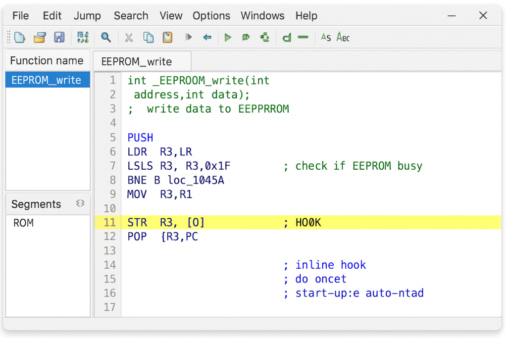
- Hooking into EEPROM Write Function: Next, we wrote a small piece of new code (often called a “hook” or handler) to save the selected map into the EEPROM. Instead of writing a whole new EEPROM driver from scratch, we leveraged the existing EEPROM write function already present in the firmware. We injected a call to this function at a point in code where the current map selection is known and stable (for instance, right when the driver switches maps, or just before power-down when the ECU can save its state). Our hook code does the following:
- Load the map selection value (a single byte representing the chosen map index) into a register.
- Call the EEPROM write routine with the address we designated for storing this byte (within the previously freed DTC area) and the value from the register.
- Return control to the normal flow.
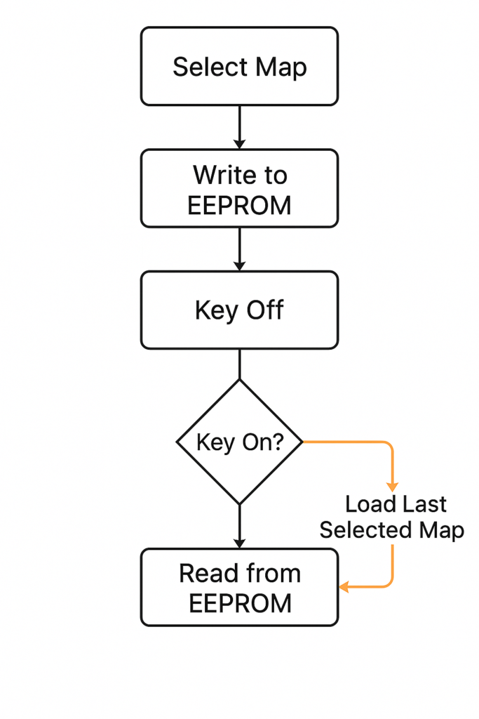
- Reading Map Selection at Startup: Writing the map selection to memory is only half of the solution – the ECU also needs to load that value when it boots up so it knows which map to use. The next implementation step was to modify the ECU’s startup initialization sequence. We inserted a patch in the initialization code (which runs at every key-on) to read the stored byte from EEPROM and set the ECU’s active map index accordingly. Concretely, this meant:
- During the early initialization (after the ECU’s self-checks, before engine management routines begin), add a call to the EEPROM read routine, targeting the address where our map byte is stored.
- Place the returned value into the variable or memory location that the ECU uses to decide which set of maps (calibrations) to use.
- If the EEPROM returns an invalid value (e.g., if for some reason the byte was never written or got corrupted), our code defaults this value to “Map 1” (the stock map) to be safe. This ensures there’s always a valid map selection in place.
- Maintaining Checksums and Safety: After making these code changes, we addressed any data integrity mechanisms. Many ECUs have checksums to detect tampering or corruption in their firmware. We calculated the new checksum for the modified firmware (or in some cases bypassed the check if we specifically patched that out) so that the ECU would accept the firmware as valid. This is a critical step: if the ECU thought the firmware was invalid, it might refuse to start the engine or enter a recovery mode. By updating the checksums, we made our patch invisible to such security measures. Additionally, we made sure our code fits in unused space or overwrote only non-essential instructions, to avoid any overflow or overlap with other functionalities. The custom code we added was very compact – just a few assembly instructions – well within the space freed by removing the DTC logging calls.
It’s worth highlighting how surgical these changes are. We didn’t rewrite large swaths of the ECU software; we inserted a couple of extra instructions and repurposed a tiny byte of memory. This minimalist approach reduces the chances of unintended side effects. Our team’s familiarity with low-level programming and ECU architectures was key to implementing the solution cleanly. By the end of this implementation phase, we had a modified firmware ready to be tested on the bench and then on the vehicle.
Testing and Validation
After coding the solution, extensive testing and validation were performed to ensure everything worked flawlessly and safely. Our testing process covered both laboratory bench tests and real-world trials, focusing on the following aspects:
- Bench Testing with Repeated Cycles: We first tested the modified ECU firmware on a bench setup. Using a bench harness to power the ECU and simulate ignition on/off cycles, we verified that the map selection persisted. We would select a non-default map (simulating the driver’s choice), power cycle the ECU, and then observe which map the ECU defaulted to on the next power-up. The expectation (and result) was that it stayed on the previously selected map every time. We repeated this many times to ensure consistency. During these cycles, we also monitored that no new error codes were being logged to the EEPROM (since that feature was disabled). This bench environment allowed us to observe the ECU’s behavior in isolation and even attach a debugger or memory reader to confirm the EEPROM content.
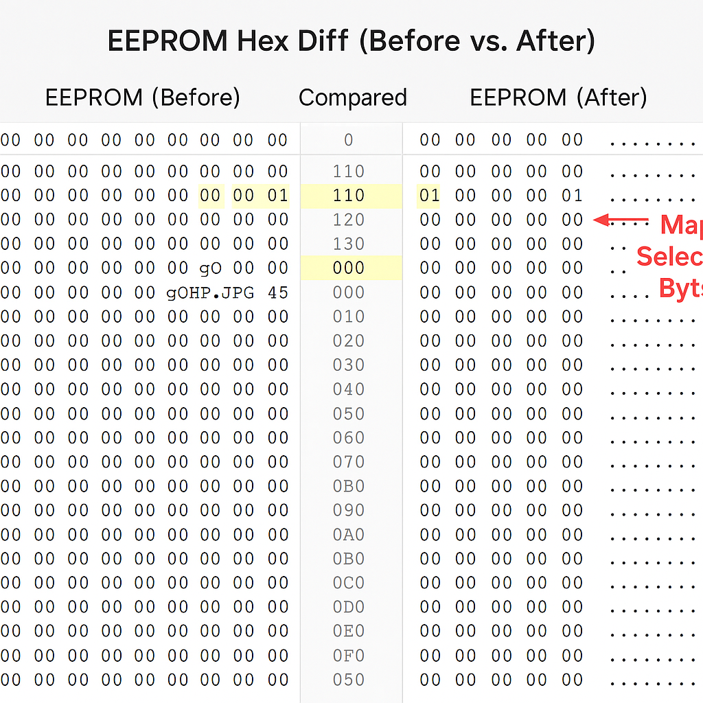
- EEPROM Content Verification: A crucial part of validation was reading out the EEPROM to confirm that our map selection byte was indeed being written and updated correctly, and that no other data was unintentionally altered. We compared the EEPROM memory contents before and after our modifications under various scenarios. The difference was exactly as expected: previously, certain EEPROM addresses would get populated with DTC data after faults; with our patched firmware, those addresses remained untouched (e.g., filled with default 0xFF bytes), and instead a specific address now held the value of the last map selection. Above: A comparison of EEPROM data before and after the patch. The “Before” side (left) shows a snapshot of the EEPROM memory after normal use – some bytes are occupied by DTC codes (non-0xFF values highlighted) and no dedicated map selection byte existed. The “After” side (right) shows the EEPROM after our firmware patch: the area once used for DTCs is now freed (all 0xFFs, meaning no error codes stored), and we can see a single byte
0x02at a specific address (highlighted in yellow) representing the stored map selection (in this example, Map #2). This confirms that our patch successfully writes and retains the chosen map index, and that no unintended data is present. We verified that aside from this intended change, the rest of the EEPROM remained identical, ensuring we didn’t disturb other settings.
- In-Vehicle Testing: Once bench tests proved the concept, the modified firmware was loaded into the actual ECU of the vehicle (a diesel vehicle equipped with the Denso ECU in question). The client performed real-world driving tests. They would switch maps via their usual mechanism (this could be a switch or a software command, depending on how the vehicle or tuning setup was configured), then turn the vehicle off, remove the key, wait a few moments, and start it again. The ECU correctly came up in the previously selected mode. We asked the client to try various sequences: switch to Map 2, key off, key on – still Map 2; switch to Map 3, immediately key off, key on – still Map 3; and also fallback scenarios like leave it on default Map 1 (no change) and verify it stays on Map 1 (which sounds obvious but is a control test to ensure default behavior wasn’t broken for those who don’t switch maps).
- Monitoring for Side Effects: During vehicle tests, we also monitored for any side effects. This included checking that the check-engine light behaved normally and that the absence of stored DTCs did not confuse the vehicle’s diagnostic system. We used an OBD-II scanner to ensure that active faults could still be read in real-time (they could, since we only disabled the permanent storage of them). The engine’s performance and idling were observed to ensure that our code changes did not inadvertently alter any other logic. The transitions between maps were smooth and as expected. In short, the car drove normally – except now it had the new convenience of remembering the chosen map.
- Stress and Endurance: We also considered the endurance of the EEPROM. Each map change writes one byte. Even if the driver switched maps every day, the number of writes is negligible for the EEPROM’s lifespan (which is often on the order of 100,000+ write cycles). We did a rough calculation to ensure this modification wouldn’t wear out the memory prematurely – it would not, by a wide margin. We also simulated rapid on-off cycles (to mimic someone starting the car multiple times in a short period) to ensure the startup read logic always grabbed the correct byte and didn’t occasionally misread due to power fluctuations or timing. The implementation proved robust in all these tests.
Through this thorough testing regimen, we gained confidence that our solution was production-ready. The Denso Diesel ECU reliably retained the map selection, and no instability or errors were introduced. In fact, to an outside observer, the ECU’s new ability felt entirely native – as if the vehicle always had this feature from the factory. This is the hallmark of a successful firmware patch in automotive systems: seamless integration.
Client Feedback
The client was extremely pleased with the outcome of the project. Initially, they approached us with a clear goal – they wanted their ECU to stop “forgetting” the chosen tune after each key-off. Throughout the collaboration, we kept them informed of our progress, and they were impressed by the rigor of our approach (from reverse engineering to validation testing). After the in-vehicle tests were completed, the client provided positive feedback, which we paraphrase here:
“It works perfectly – my truck now always starts in the mode I last left it in. I no longer have to re-select the performance map every morning. The transition is seamless, and I haven’t encountered any issues or warning lights. It really feels like this is how the ECU was meant to function. Great job making it look easy!”
They particularly appreciated that we managed to implement the feature without adding any external hardware or switches. Everything is internal to the ECU, which means the solution is invisible and maintenance-free from the user’s perspective. The client also noted peace of mind knowing that if they ever needed to revert the change (for example, for dealership service), it could be done by simply restoring the original firmware file – a testament to how non-intrusive our modifications were.
Moreover, the client’s confidence in ReverseEngineer.net was bolstered by our clear communication and expertise. We took the time to explain the technical details in an accessible way when presenting the solution, which helped them understand the value of what was delivered. By delivering a solution that met their needs and was thoroughly tested, we built a strong trust with the client. In fact, they indicated interest in future projects, now that they saw what could be achieved with custom ECU firmware patches.
Conclusion and Contact Invitation
This project showcases ReverseEngineer.net’s expertise in firmware patching, reverse engineering, and embedded systems development for automotive applications. We successfully added a new capability to an OEM ECU – preserving map selection across restarts – all while maintaining the original stability and reliability of the system. From reclaiming memory space in an EEPROM to injecting custom assembly code, every step required precision and deep technical know-how. The end result for the client was a tailor-made feature that enhanced their driving experience, delivered with OEM-like quality.
At ReverseEngineer.net, we pride ourselves on tackling exactly these kinds of challenges. Modern ECUs are sophisticated and often locked down, but as this case study demonstrates, our team has the skills to unlock, analyze, and modify vehicle firmware to meet unique needs. Whether it’s enabling new functionality, removing unwanted behaviors, or improving performance, we approach each project methodically – balancing innovation with caution to ensure safety and reliability.
Interested in a similar solution for your project? If you have an embedded system or ECU challenge – be it in the automotive realm or any other industry – our engineers are ready to help. We invite you to reach out and discuss how we can apply our reverse engineering and development expertise to turn your ideas into reality.
Contact us today via our contact form to start a conversation about your project’s needs. Let’s collaborate to reverse engineer your success story.Let's Work Together
Need Professional Assistance with Reverse Engineering or Cybersecurity Solutions? Our Team is Ready To Help You Tackle Complex Technical Challenges.