ECU Bench Mode: Why It Matters
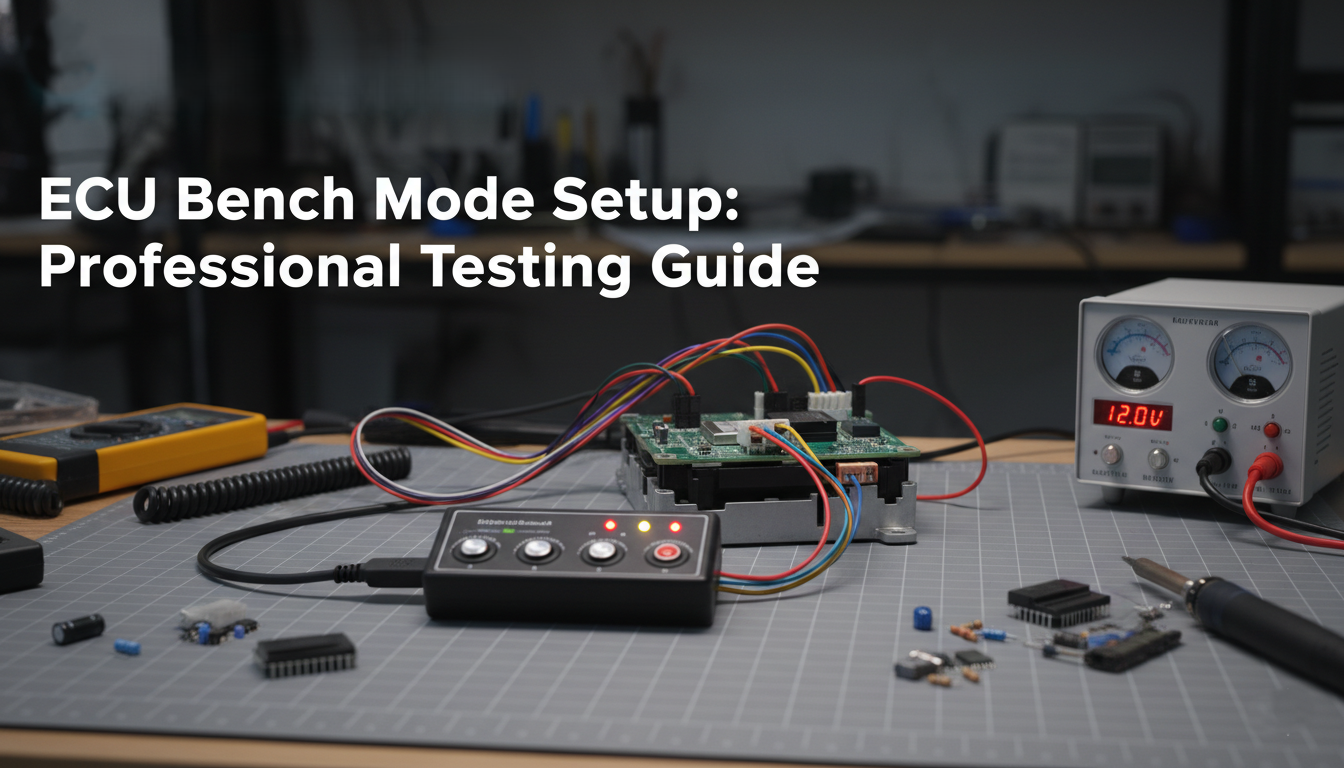
Working with an ECU outside the vehicle is fundamental to professional reverse engineering, tuning development, and security research. ECU bench mode setup is the process of powering and communicating with an ECU on a workbench, disconnected from the car, in a controlled and repeatable environment. Whether you are developing calibration modifications, analyzing firmware security, or performing forensic examination, a proper bench setup is the foundation that everything else depends on.
At ReverseEngineer.net, bench mode operation is how we spend most of our working hours. Every ECU that arrives at our lab goes through a bench setup process before any analysis begins. Over years of working with dozens of ECU platforms, we have refined our bench procedures to be safe, reliable, and efficient. This article covers the key principles, hardware requirements, and platform-specific considerations that define a professional ECU bench mode setup.
Power Supply: The Most Critical Component
The single most important element of any ECU bench mode setup is the power supply. ECUs are designed to operate within a specific voltage window, typically 9V to 16V, with a nominal operating point of 13.8V (simulating a running vehicle with alternator charging). Getting this wrong is the fastest way to damage expensive hardware.
Power Supply Requirements
| Parameter | Recommended Value | Why It Matters |
|---|---|---|
| Voltage | 13.8V DC (adjustable 9-16V) | Simulates vehicle alternator charging voltage |
| Current capacity | 5A minimum, 10A preferred | Some ECUs draw 3-4A during boot or flash operations |
| Current limiting | Adjustable, set to 5A initially | Protects against wiring errors and short circuits |
| Ripple / noise | Low ripple (linear or filtered switching) | Noisy supplies can cause CAN errors and erratic behavior |
| Protection | OVP, OCP, reverse polarity | Essential safety features for bench operations |
A laboratory-grade adjustable DC power supply with current limiting is the correct choice. Cheap unregulated supplies, modified laptop chargers, or battery chargers are not suitable. The voltage must be clean and stable. Many ECUs monitor their supply voltage internally and will refuse to enter programming mode or will shut down internal flash operations if the voltage drops below a threshold during a write cycle. An interrupted flash operation caused by an unstable power supply can leave an ECU in an unrecoverable state.
We also recommend adding a large electrolytic capacitor (2200uF to 4700uF, rated for at least 25V) across the power input close to the ECU connector. This helps absorb current transients when the ECU activates internal loads during boot, which some switching power supplies handle poorly.
CAN Bus Interface and Communication
Nearly all modern ECUs communicate through the CAN bus. For bench mode operation, you need a reliable CAN interface connected to the correct CAN channel on the ECU. Most engine ECUs use a high-speed CAN bus (500 kbps), though some body-side or older platforms may use 250 kbps or even single-wire CAN.
CAN Wiring Essentials
The CAN bus requires proper termination to function correctly. In a vehicle, the bus is terminated by 120-ohm resistors at each end of the physical bus. On the bench, you need to provide this termination yourself. The standard approach is a single 120-ohm resistor between CAN-H and CAN-L at the ECU connector end, and a second 120-ohm resistor at or inside the CAN interface adapter. Many professional CAN interfaces (Peak PCAN, Kvaser, Vector CANcase) include switchable internal termination. If your interface does not, solder a 120-ohm resistor into your bench harness.
Without proper termination, you will see intermittent communication failures, CRC errors, or complete inability to establish a diagnostic session. This is one of the most common mistakes in ECU bench mode setup, and it wastes hours of troubleshooting time when the fix is a single resistor.
Setting up a professional ECU bench lab? We provide consulting on bench infrastructure, custom harness design, and tool selection for professional ECU development and reverse engineering environments.
Bench Harness: Wiring It Right
A bench harness is the wiring adapter that connects your power supply and CAN interface to the ECU’s connector. For professional work, investing in proper bench harnesses saves enormous amounts of time and prevents wiring errors that can destroy ECUs.
The minimum connections required for most ECU bench mode setups are:
- Battery positive (B+): Permanent 12V supply to the ECU
- Ignition (KL15): Switched 12V, simulates the ignition-on signal
- Ground(s): Multiple ground pins, all must be connected (ECUs typically have 2-4 ground pins serving different internal circuits)
- CAN-H and CAN-L: Communication bus with proper termination
- K-Line (if applicable): Some older platforms still use K-Line for diagnostics or programming
Some ECUs require additional connections to boot normally. The Bosch MED17/EDC17 family, for example, may need specific sensor simulation signals (like a crank sensor pulse or a cam sensor signal) to exit a limited boot mode. Continental Simos units generally boot without sensor simulation, making them more bench-friendly. Delphi platforms vary depending on the vehicle integration.
The Ignition Sequence
Proper power-on sequencing matters. The correct procedure for most ECUs is:
- Connect all ground wires first
- Apply B+ (permanent battery voltage) and verify current draw is minimal
- Apply KL15 (ignition signal) to wake the ECU
- Wait for CAN communication to appear (usually within 500ms to 2 seconds)
- Begin diagnostic session
Reversing this order, or applying ignition before battery voltage, can cause undefined behavior on some platforms. Always power down in reverse order: remove KL15 first, wait for the ECU to complete its shutdown sequence (5-10 seconds), then remove B+.
Platform-Specific Bench Mode Considerations
Different ECU processor architectures have specific requirements for bench mode activation, particularly when the goal is firmware extraction or low-level debug access rather than simple diagnostic communication.
Infineon TriCore (Bosch MED17, Continental Simos)
TriCore-based ECUs use specific boot mode pin configurations to enter BSL (Bootstrap Loader) mode. This typically involves pulling certain processor pins to defined voltage levels during the power-on reset sequence. On Bosch MED17 units, the boot mode pins are accessible through test points on the PCB, and the exact pin configuration varies by hardware version. TriCore BSL mode allows low-level flash read and write operations over the processor’s debug interface, bypassing the normal application-level security. Accessing these pins requires opening the ECU case and, in many cases, soldering fine-pitch wires to the PCB.
Renesas RH850 (Bosch MDG1, Denso platforms)
RH850-based ECUs enter their programming mode through the FLMD0 pin, which must be pulled high during reset to activate the flash programming environment. The RH850 programming protocol operates over UART or CSI (serial), not CAN, which means your bench harness needs an additional serial connection to the correct pins on the processor. The baudrate and protocol handshake differ between RH850 variants (D1x vs. E1x vs. F1x families).
ST Micro SPC56 (Delphi, Marelli, some Bosch)
SPC5-based ECUs use the BAM (Boot Assist Module) for low-level programming access. The SPC56 BAM is activated by driving the BOOTCFG pin configuration during reset. Depending on the specific SPC5 variant, BAM communication can occur over CAN, LINFlex (UART), or FlexRay. The BAM provides basic flash erase and program capabilities, but the censorship bits must be handled correctly, or you will be locked out of the flash contents.
Need professional bench mode support for a specific ECU? Whether it is boot pin identification, custom harness fabrication, or full firmware extraction, our lab handles every major ECU platform. Contact us for a consultation.
Common Mistakes and How to Avoid Them
Years of bench work have taught us the failure modes that cause the most damage and wasted time. Here are the most frequent mistakes we see:
| Mistake | Consequence | Prevention |
|---|---|---|
| Reverse polarity on power | Immediate destruction of internal voltage regulators | Use a fused harness with polarity protection diode |
| Missing ground connections | Ground loops, erratic behavior, CAN errors | Connect ALL ground pins, not just one |
| No CAN termination | Intermittent or no communication | Always verify 60 ohms total resistance on CAN bus |
| Unstable supply during flash | Bricked ECU (corrupted flash) | Use regulated supply with bulk capacitor, never interrupt power during write |
| Wrong CAN baudrate | No response from ECU, misdiagnosed as hardware fault | Check vehicle-specific documentation; try 500k first, then 250k |
| Powering on with boot pins shorted | Unintended boot mode entry, potential security lockout | Only manipulate boot pins when you know the exact procedure |
Tools of the Trade
A professional ECU bench mode setup requires a specific set of tools. The quality of these tools directly affects the reliability and safety of your bench operations.
- Adjustable DC power supply (30V/10A): A laboratory-grade supply with voltage and current readout is essential. Models with programmable output, over-voltage protection, and remote sense capability are ideal for repetitive testing.
- CAN interface adapter: Professional-grade adapters like Peak PCAN-USB, Kvaser Leaf, or Vector CANcase provide reliable communication and proper driver support. Avoid cheap no-name USB-CAN adapters for critical operations.
- Oscilloscope: A basic 2-channel digital scope is invaluable for verifying CAN signal integrity, checking power supply quality, and debugging boot mode timing.
- Multimeter: Essential for continuity checking, voltage verification, and resistance measurement on CAN termination.
- Bench harness kit: Either commercially available harnesses for specific ECU families, or custom-built harnesses with proper automotive-grade connectors and fused wiring.
- ESD protection: Anti-static mat, wrist strap, and proper grounding. ECU components are sensitive to electrostatic discharge, and a single ESD event can cause latent damage that manifests as intermittent failures later.
For firmware extraction work specifically, additional tools may be needed depending on the processor: JTAG/SWD debug probes (J-Link, PEmicro Multilink), BDM adapters for PowerPC targets, or specialized boot mode adapters. The exact toolchain depends on the target processor architecture, which we have covered in detail in our articles on TriCore, RH850, and SPC56 architectures.
From Bench to Results
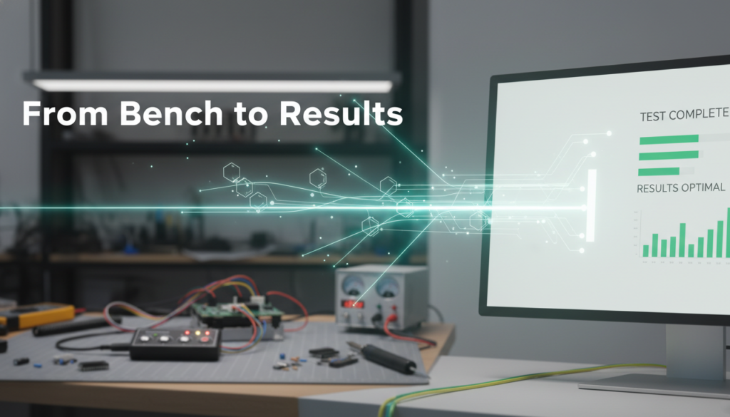
A well-built bench setup is not the end goal; it is the prerequisite for everything that follows. Once the ECU is communicating reliably on the bench, the real work begins: firmware extraction, reverse engineering analysis, calibration development, security research, or forensic examination. Every one of these tasks depends on a bench environment that is stable, repeatable, and safe.
The difference between an amateur bench setup and a professional one becomes obvious the first time something goes wrong. A fused harness limits damage. A current-limited supply catches wiring mistakes before they destroy components. Proper CAN termination eliminates phantom communication errors. These are not optional refinements; they are the baseline requirements for anyone doing serious ECU work. Getting the bench right means you can focus your time and expertise on the actual analysis, which is where the value lies.
Let's Work Together
Need Professional Assistance with Reverse Engineering or Cybersecurity Solutions? Our Team is Ready To Help You Tackle Complex Technical Challenges.