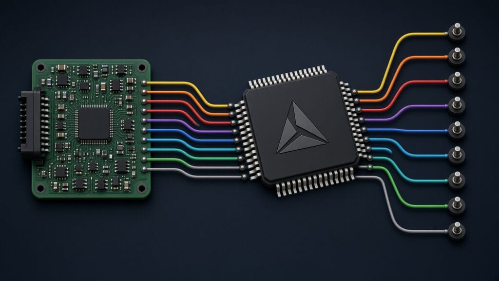
ECU boot mode activation is one of the most critical steps in automotive firmware extraction. When standard diagnostic protocols are locked down, when read protection fuses block JTAG access, or when the OBD interface has been disabled, boot mode often remains the last viable path to reading the firmware from an ECU. Every major automotive processor family, from Infineon TriCore to Renesas RH850 to NXP MPC5xxx, includes some form of built-in boot loader that can be activated through specific pin configurations at power-up. Understanding how to trigger these modes, and what happens after activation, is fundamental to professional ECU reverse engineering.
This article covers the boot mode mechanisms for the processor families most commonly found in modern engine control units. We explain the underlying hardware logic, the activation requirements, and how boot mode fits into the broader firmware extraction workflow.
Why Boot Mode Matters
Modern ECUs implement multiple layers of access protection. The UDS diagnostic protocol requires SecurityAccess authentication before allowing firmware read operations. JTAG and debug interfaces are often disabled through hardware fuses or software configuration. Some ECUs encrypt the firmware stored in external flash. In many cases, the only way to access the raw firmware binary is through the processor’s built-in boot loader, which operates below the level of these software protections.
Boot mode activation forces the processor to bypass its normal startup sequence. Instead of executing the application firmware from flash memory, the processor enters a minimal loader state that accepts commands over a serial interface (typically UART, SPI, or CAN). This loader can read flash contents, write new data, and in some cases erase or reconfigure memory protection settings. The boot loader exists because the chip manufacturer needs a way to program blank devices during production, and that same mechanism becomes the entry point for firmware extraction and recovery.
| Processor Family | Boot Mode Name | Activation Method | Communication Interface |
|---|---|---|---|
| Infineon TriCore (TC1xx/TC2xx/TC3xx) | BSL (Boot Strap Loader) | Pin configuration at reset | CAN, UART, or ASC |
| Renesas RH850 | Serial Boot Mode | FLMD0 pin held high at reset | UART (LIN-compatible) |
| ST SPC56x / SPC58x | BAM (Boot Assist Module) | Censorship control / FAB pin | CAN, UART (LINFlex) |
| NXP MPC55xx / MPC56xx / MPC57xx | BAM (Boot Assist Module) | BOOTCFG pins / censorship | CAN, FlexCAN, eSCI |
Infineon TriCore BSL: The Most Common ECU Boot Mode
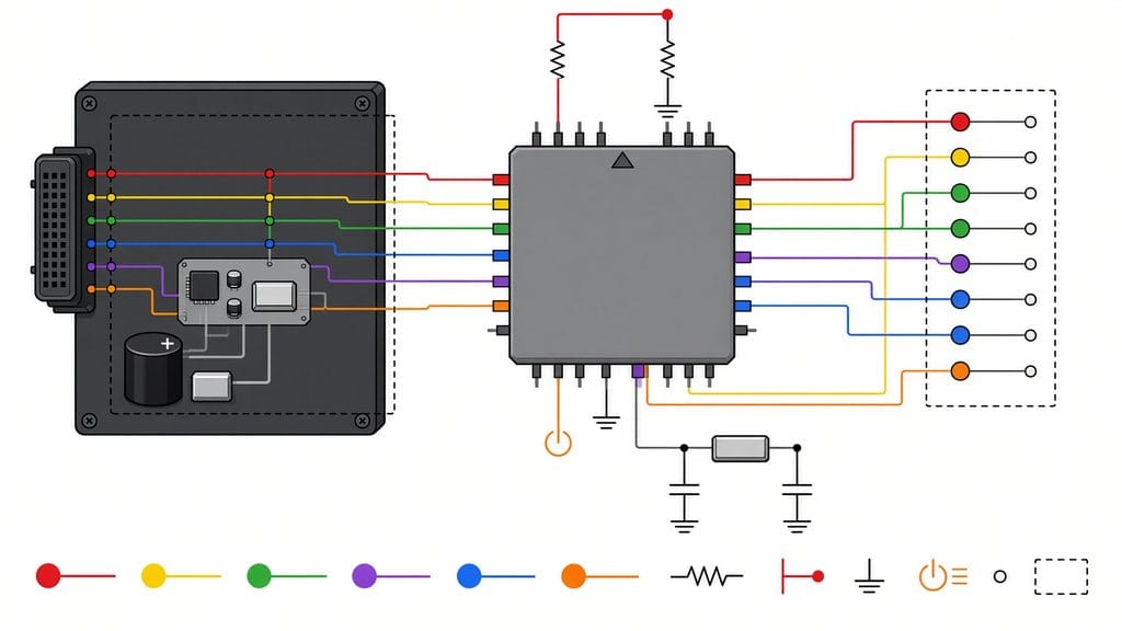
Infineon TriCore processors dominate the automotive ECU landscape, powering the majority of Bosch MED17 and EDC17 units as well as many Continental and other tier-1 supplier platforms. The TriCore Boot Strap Loader (BSL) is the built-in mechanism for initial device programming and firmware recovery.
The BSL is activated by setting specific pin states during the processor reset sequence. The exact pins vary by TriCore generation. On TC17xx devices, the HWCFG pins (typically HWCFG[0:1]) determine the boot source when the device exits reset. Setting these pins to the BSL configuration forces the processor to enter its internal boot loader rather than executing from flash. On newer TC2xx and TC3xx devices, the mechanism involves the boot mode header and the state of configuration pins at the rising edge of the PORST (Power-On Reset) signal.
Once BSL mode is active, the TriCore listens for communication on a predefined interface, most commonly CAN or ASC (asynchronous serial). The boot loader protocol supports a set of commands for reading memory regions, writing data to RAM and flash, and executing code from RAM. The protocol uses a structured message format with command identifiers, address parameters, and data payloads.
There are important nuances that determine what BSL access actually provides. On devices where User Configuration Blocks (UCBs) have been programmed with password protection, the BSL may require a valid password before granting full read access to flash memory. On devices with activated read protection (Tuning Protection or Debug Protection), BSL access may be restricted to write-only operations, preventing firmware readout without the correct credentials. The exact protection behavior varies by TriCore generation and UCB configuration, and understanding these protection levels requires detailed knowledge of the specific silicon variant.
TriCore BSL access and protection bypass require precise knowledge of the specific processor variant, UCB configuration, and protection state. Our team works with all TriCore generations across multiple ECU platforms. Reach out to discuss your TriCore-based ECU project.
Renesas RH850: Serial Boot Mode Activation
The Renesas RH850 family, widely used in Denso and Continental ECUs as well as various Japanese and Korean OEM platforms, implements a serial programming mode activated through a dedicated pin.
ECU boot mode activation on the RH850 centers on the FLMD0 (Flash Mode 0) pin. When this pin is held at a logic high level during the processor’s reset sequence, the device enters its internal flash programming mode instead of normal execution. Some RH850 variants include a secondary FLMD1 pin that, in combination with FLMD0, selects between different boot mode options such as serial programming versus test mode.
In serial boot mode, the RH850 communicates over a UART interface running at a baud rate that is initially auto-detected through a synchronization sequence. The host sends a specific sync byte pattern, the RH850 measures the timing to determine the baud rate, and once synchronization is established, the full command protocol becomes available. This protocol supports flash memory operations including read, write, erase, and blank check, along with device identification commands that report the specific RH850 variant and its flash configuration.
The practical challenge with RH850 boot mode in an ECU context is accessing the FLMD0 pin. On the actual ECU board, this pin is typically connected to a pull-down resistor to ensure normal boot during standard operation. Activating boot mode requires either locating the FLMD0 trace on the ECU PCB and applying a voltage override, or finding a test point or pad that provides access to this signal. This is where PCB reverse engineering becomes essential: the board layout must be analyzed to identify the correct point without risking damage to surrounding components.
RH850 security features add another layer of complexity. Many RH850 variants support an ID code authentication mechanism where the boot loader requires a matching 16-byte code before granting read access to protected flash regions. If the ID code has been set by the ECU manufacturer and is not known, boot mode alone does not guarantee firmware readout. Additional analysis or alternative approaches may be required.
ST Microelectronics SPC56x: Boot Assist Module
The SPC56x and SPC58x families from ST Microelectronics are found in a range of European automotive ECUs, particularly in body control modules, transmission controllers, and some engine management applications. These processors implement a Boot Assist Module (BAM) that serves the same function as the TriCore BSL.
BAM activation on SPC56x devices depends on the censorship control configuration and the state of the FAB (Force Alternate Boot) pin. In an uncensored device, pulling the FAB pin to the appropriate level during reset forces the processor into BAM mode. The BAM then listens for incoming communication on CAN or the LINFlex UART peripheral, waiting for a valid boot command sequence.
The SPC56x BAM protocol begins with an auto-baud detection phase on UART or a specific CAN frame exchange. Once communication is established, the BAM supports downloading code to internal RAM and executing it. This is a different model from the TriCore BSL or RH850 serial boot: rather than providing built-in flash read/write commands, the SPC56x BAM loads and runs a custom program in RAM. That program, supplied by the user, then performs whatever flash operations are needed. This means the host tool must provide the appropriate flash programming routines, which requires knowledge of the specific SPC56x variant’s flash controller registers and programming sequences.
When censorship is active on an SPC56x device, BAM access is restricted. The censorship mechanism protects the flash contents from unauthorized reading. Bypassing or working within these restrictions requires understanding the censorship implementation, the password mechanism (if one exists), and the specific protections applied to the device.
NXP MPC5xxx: A Legacy That Still Matters
The NXP (formerly Freescale) MPC55xx, MPC56xx, and MPC57xx families have a long history in automotive ECUs. While newer designs are transitioning to ARM-based platforms, millions of MPC5xxx-based ECUs remain in service, and many current-production vehicles still use these processors. Understanding MPC5xxx ECU boot mode activation remains highly relevant.
The MPC5xxx BAM operates similarly to the SPC56x approach, which makes sense given the shared PowerPC architecture heritage. Boot mode is selected through the BOOTCFG pin configuration sampled at reset. The BAM supports communication over FlexCAN and eSCI (Enhanced Serial Communication Interface) peripherals. Like the SPC56x, the MPC5xxx BAM downloads a user-supplied program to RAM for execution rather than providing native flash access commands.
The censorship model on MPC5xxx devices involves a censorship control word stored in the flash configuration area. When censorship is enabled, access to flash contents through BAM, JTAG, and Nexus debug interfaces is restricted. The censorship password mechanism allows authorized access if the correct password is supplied. On some older MPC55xx variants, censorship implementations had known weaknesses that could be exploited for firmware recovery. Newer MPC56xx and MPC57xx devices have significantly improved censorship security.
For advanced firmware reverse engineering on MPC5xxx platforms, boot mode access often works in combination with other techniques. The BAM provides the initial foothold, and custom code loaded through BAM can then interact with the processor’s debug facilities, flash controller, or CAN bus interfaces to achieve the specific extraction or analysis goals.
ECU boot mode activation requires processor-specific knowledge, proper hardware setup, and careful handling of security features. If you need firmware extracted from a protected ECU, our team has hands-on experience with all major automotive processor families. Contact us with your ECU details.
The Hardware Side: What Boot Mode Activation Looks Like in Practice
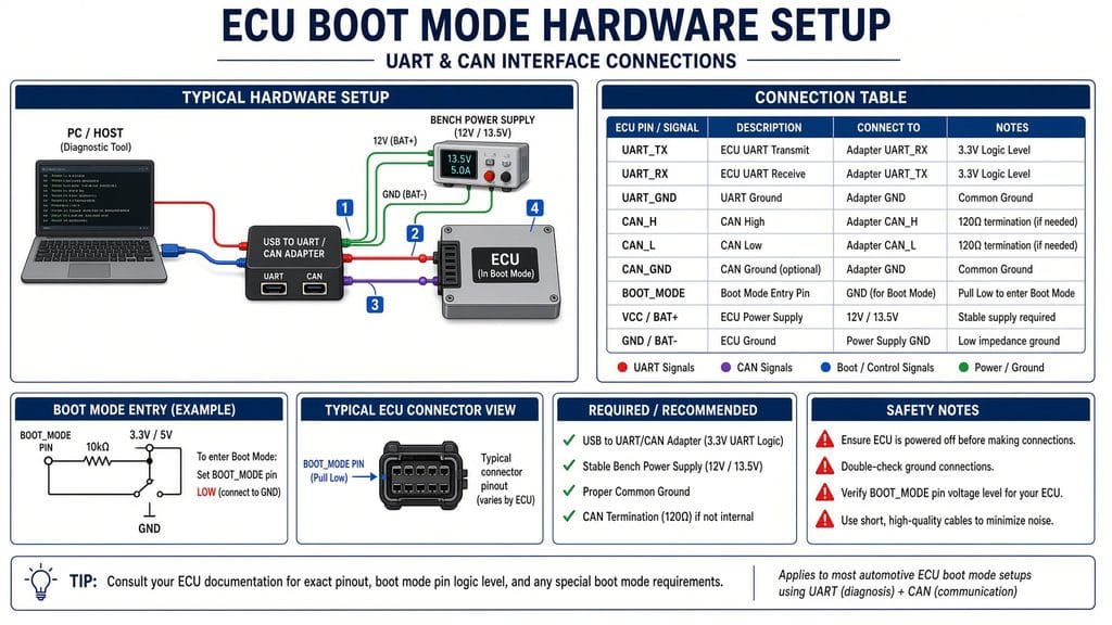
Triggering boot mode on an ECU is not as simple as connecting a cable and pressing a button. It requires physical access to the ECU circuit board and, in most cases, soldering or probing specific pins or test points. The general process involves:
PCB analysis: The ECU board must be examined to identify the processor, locate the boot mode configuration pins, and trace the relevant signals. This often requires removing conformal coating and using a microscope or magnification to read component markings and trace routes.
Pin access: Once the boot mode pin is identified, a connection must be made. On some ECUs, test points or unpopulated pads provide convenient access. On others, fine-pitch soldering directly to the processor’s pin or an associated via is necessary. The pitch on modern BGA packages can be as tight as 0.5mm, requiring steady hands and proper equipment.
Timing and sequencing: Boot mode pins are sampled at a specific point during the reset sequence. The pin must be at the correct logic level before the processor’s reset is released, and it must remain stable through the sampling window. Some processors sample on the rising edge of the reset signal; others sample after a fixed delay. Getting the timing wrong means the processor boots normally and the boot loader is never activated.
Communication setup: With boot mode active, the appropriate communication interface (UART adapter, CAN interface, or SPI bridge) must be connected to the correct pins on the ECU, configured at the right voltage level (typically 3.3V or 5V depending on the processor I/O standard), and running the correct protocol software.
Boot Mode in the Context of ECU Security
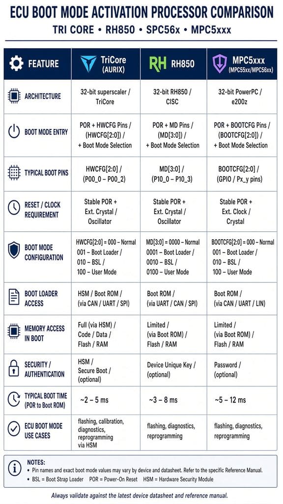
It is worth noting that ECU manufacturers are well aware that boot mode is used for firmware extraction, and each new processor generation implements stronger protections. TriCore TC3xx devices have more robust UCB password protection than TC1xx. Recent RH850 variants use stronger ID code mechanisms. Newer SPC58x and MPC57xx chips implement hardware security modules (HSMs) that can enforce protections even at the boot loader level.
This escalation means that boot mode activation alone is rarely sufficient for protected devices. It is typically one component of a multi-step process that may include security credential recovery, custom boot loader development, glitch-based attacks, or static analysis of available firmware samples to understand protection mechanisms before attempting extraction on the target device.
ECU boot mode activation remains an essential technique in the firmware extraction toolkit. Whether you are working with a TriCore-based Bosch unit, an RH850-based Denso controller, or an SPC56x-based body module, the boot loader provides a hardware-level access path that operates independently of the application firmware and its software protections. Leveraging that access effectively requires deep knowledge of the specific processor, the ECU’s hardware design, and the security measures in place.
Let's Work Together
Working on an ECU, a firmware image, or a board? Send what you have.