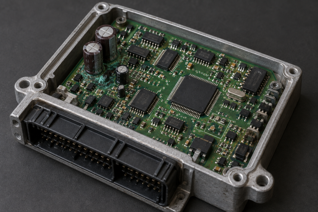
For an ECU remanufacturer, the difficult LS400 job is not necessarily the board with an obviously failed capacitor. It is the board with damaged copper, uncertain previous repairs and no trustworthy record of how the affected circuit should behave. Replacing visible components may restore communication without establishing that an input is accurate or an output is reliable. Returning that unit to service without a defined test creates a warranty risk that a visual inspection cannot resolve.
The useful engineering output is a reconstructed circuit and a way to test it repeatedly. ReverseEngineer.net can scope this work around a damaged region, a recurring fault pattern or a family of identified board revisions. The objective is to turn an undocumented repair into a reviewable process: which connections are confirmed, which component functions are understood, what can be repaired and which observations justify accepting the result.
The real problem extends beyond a capacitor list
LS400 owners have reported capacitor leakage accompanied by suspected damage to small surrounding components, as illustrated by this owner discussion about an ECU replacement decision. That report establishes a practical problem people encounter; it does not establish the cause of every LS400 fault. Each incoming controller still needs its own inspection and electrical diagnosis.
This article addresses circuit reconstruction and remanufacturing test coverage. Our earlier Prado ECU investigation after recapping addresses the different question of diagnosing a unit that remains faulty after component replacement. A repair business handling repeated LS400 work needs an additional deliverable: knowledge that another technician can apply to the same verified board revision without rediscovering the circuit each time.
Define the board family before building a repair standard
Record the housing label, board markings, connector arrangement, component population and any evidence of earlier rework. A known-good comparison unit is useful only when its relationship to the damaged board is established. Similar packaging does not prove that component values, routing or firmware behavior are identical. A production repair standard should identify its supported revisions and explain how an unfamiliar revision is handled.
The intake record should distinguish customer symptoms from bench observations. An intermittent engine symptom, a diagnostic communication failure and visible contamination are different pieces of evidence. Photographs should preserve both board surfaces before rework obscures the original damage. If the board already contains jumpers or replacement components, record those as unverified interventions until their function has been checked.
Recover connectivity as a set of testable claims
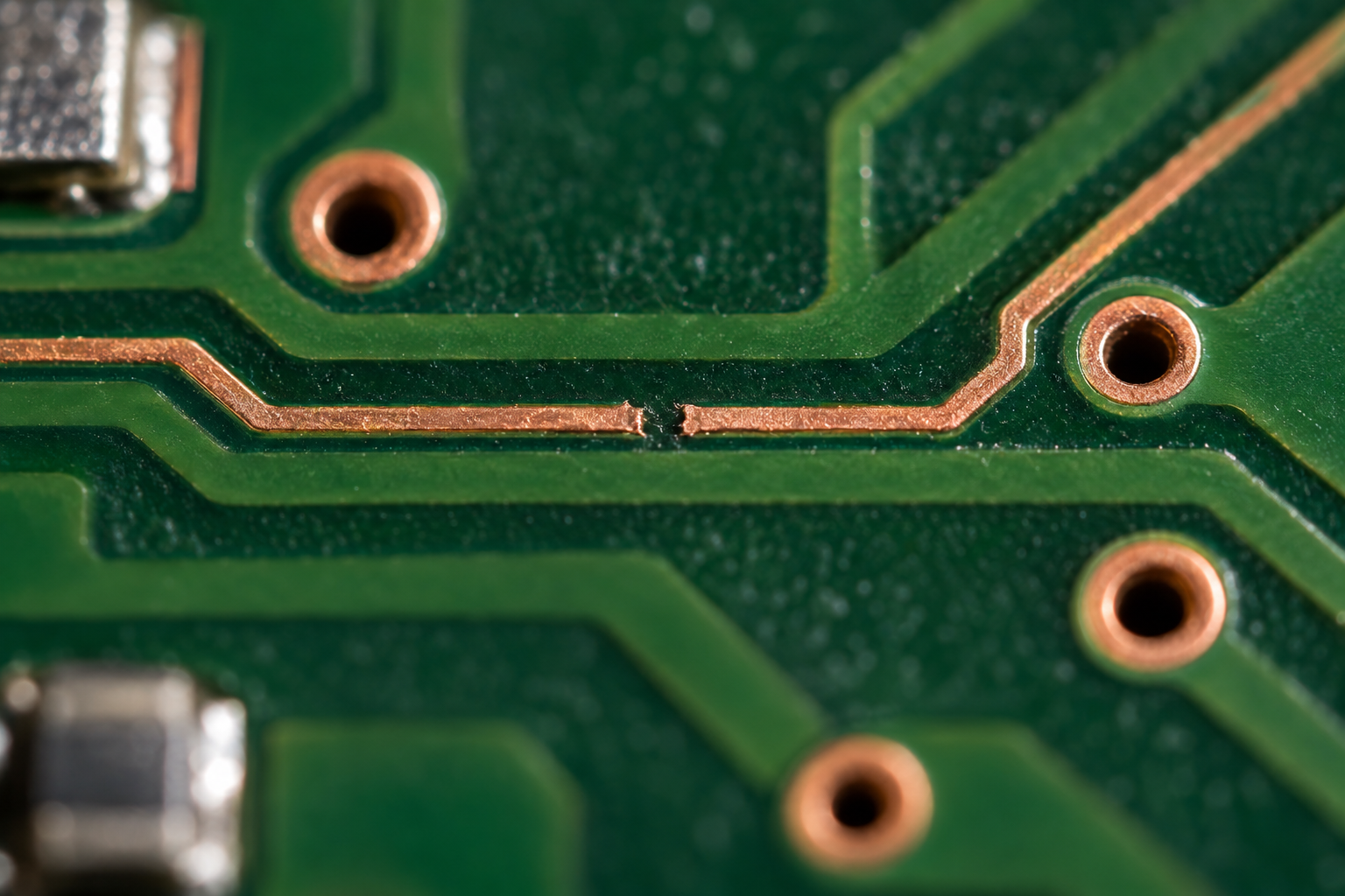
A partial schematic starts with a question, such as how a particular connector input reaches its conditioning circuit. Trace the accessible path through protection, filtering, bias components and the receiving device. Assign temporary net names where the original names are unknown. Each connection should carry its evidence: directly visible copper, repeatable electrical measurement, a matched reference board or a hypothesis that still needs confirmation.
In-circuit continuity needs interpretation. A meter can indicate a path through a resistor, protection device or parallel circuit without proving a direct copper connection. Likewise, a via that looks intact may not establish connectivity to the relevant internal layer. The netlist should not treat every audible continuity indication as the same kind of connection. The measurement conditions and expected component paths matter.
The deliverable should preserve uncertainty explicitly. A confirmed connection can be used to plan a repair; an inferred connection can guide the next measurement. If an internal route cannot be resolved from the available board and reference material, that is a decision point. Additional imaging or another reference board may be justified, while guessing a jumper endpoint would undermine the entire repair standard.
Distinguish an open circuit from an unwanted leakage path
Corrosion investigation must consider missing connections and unintended ones. An open trace may be visually apparent, but leakage between a sensitive node and an adjacent rail can change behavior without producing an obvious short. NXP’s AN1282 identifies contamination, humidity, flux and leaky components as possible leakage sources in its example circuit. Its device-specific limits are not LS400 test limits; the relevant lesson is to investigate unwanted conduction as well as continuity.
Sensitivity depends on the surrounding circuit. For a simplified linear example, 100 nA of unwanted current acting through a 50 kΩ equivalent source resistance produces a 5 mV shift. This is an illustrative calculation, not a measured LS400 value or an acceptance threshold. It explains why a board can pass a coarse continuity check while a high-impedance measurement path remains inaccurate. Texas Instruments discusses the underlying effect in its leakage-current training.
Reconstruct circuit function, not just copper geometry
A jumper that reconnects two points does not automatically restore the intended circuit. Determine whether the damaged path carries a supply, a reference, an analog signal, a digital edge or a switched load. Its role affects the significance of resistance, routing, filtering and coupling. A repair specification should explain the function being restored so that a technician can recognize when a superficially similar repair is electrically different.
Component identification also needs a confidence level. A marking may identify a family without establishing the exact value or variant. Measurements taken in circuit can include parallel paths. Comparison against a validated reference can help, but a reference board with unknown repair history should not become an unquestioned standard. The parts list should separate verified replacements from unresolved items that prevent release.
Use firmware observations to connect electrical tests to behavior
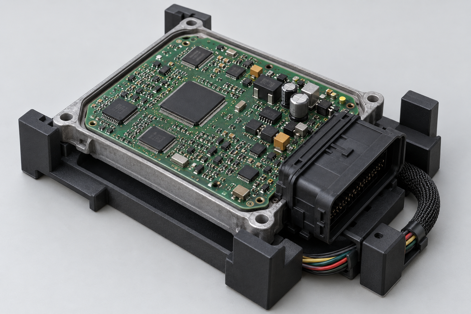
Where readable firmware and suitable analysis are available, software can help identify how a signal is used. A conditioning circuit may feed an analog conversion path, a threshold decision or a timing input. Following the relevant code can clarify whether a diagnostic value represents a raw measurement, a filtered quantity or a substituted value after fault detection. That distinction changes what a useful bench test must observe.
A plausible diagnostic value is not sufficient proof of a repaired input. It may be limited, filtered or replaced by a fallback value. A stronger test correlates a controlled electrical stimulus with the appropriate internal or diagnostic observation across the intended range. The scope must specify what is accessible and what remains indirect. Firmware analysis is worthwhile when it resolves this ambiguity, rather than being added to every board repair automatically.
Create a coverage matrix for the reconstructed region
For each reconstructed function, define the stimulus, observation, expected relationship and failure condition. An input-path test may need several points rather than one nominal value. A supply-path test may need a relevant load condition rather than an unloaded voltage measurement. An output test needs an appropriate controlled load and an observation that distinguishes command generation from the electrical response. Exact levels must come from the identified circuit and applicable limits.
Coverage should be stated honestly. Testing one input does not qualify neighboring channels, and stable communication does not qualify all output stages. A report can identify tested functions, indirectly checked functions and untested functions. This is more useful to a remanufacturer than a single pass label whose meaning changes with the technician. It also helps determine whether additional fixture development would reduce expensive returns.
Establish limits from evidence and measurement uncertainty
A known-good unit provides a comparison, but one sample does not define every acceptable production variation. Test limits should consider the circuit’s intended behavior, component tolerances, measurement uncertainty and the range of supported revisions. Where only comparative evidence exists, document that limitation. Avoid converting one observed voltage into an exact universal acceptance value.
The fixture itself can introduce errors. Contact resistance, stimulus accuracy, probe loading and test sequencing may influence the result. A repeatability check should distinguish variation caused by the fixture from variation in the ECU. If a result changes after reconnecting the same unit, that is a test-system problem to investigate before tightening rejection thresholds. A reliable process measures the controller rather than the inconsistency of its connections.
Choose between repair, reference acquisition and rejection
Not every damaged board is commercially recoverable. The assessment may support a localized repair, require additional reference evidence, or show that the unresolved damage exceeds the agreed scope. A useful report explains the reason: uncertain internal connectivity, unidentified component function, unstable measurements or insufficient functional coverage. This allows the repair business to price and route the job on evidence.
The economic value of reconstruction increases when the knowledge applies to a repeatable board family. A partial schematic, annotated images, a verified parts list and an acceptance procedure can become controlled workshop assets. Their applicability must remain versioned, so a later board change does not silently invalidate the process. The investment is in reducing repeated uncertainty across suitable units, not promising that every corroded ECU can be saved.
Commission an ECU circuit reconstruction project
For a scoped assessment, provide the exact ECU and board identification, clear pre-repair images, symptoms, previous interventions and available reference hardware. Describe whether you need a decision on one rare controller or a repeatable remanufacturing process. Our ECU reverse engineering services can combine circuit investigation, firmware interpretation and test development where the evidence supports that scope.
Contact ReverseEngineer.net with the damaged region and the function your current test cannot verify. A practical proposal can define the reconstruction boundary, required reference material and acceptance evidence before implementation begins. For the broader board-analysis workflow, see our ECU PCB reverse engineering guide.
Let's Work Together
Working on an ECU, a firmware image, or a board? Send what you have.