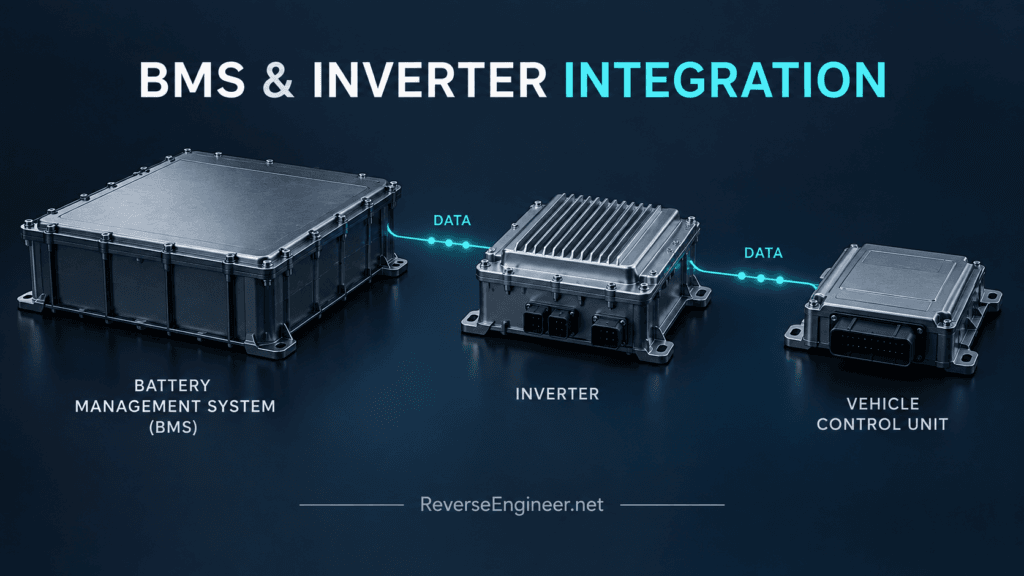
An EV development project can have a functioning battery management system, inverter and vehicle controller that still fail to work together. Each component may interpret operating state, limits and communication loss differently. BMS and inverter CAN integration requires those expectations to be understood before a gateway or control interface can be trusted.
This is relevant to prototype vehicle developers, specialist integrators and equipment manufacturers combining controllers that were not originally designed as one system. The valuable engineering output is a documented behavioural interface that can be implemented and tested.
Start with the intended operating architecture
Before decoding traffic, identify which controller owns each decision. The BMS may report battery conditions and allowable limits, while other controllers determine how those limits affect the requested operation. Those responsibilities must be established for the actual components being integrated.
Some BMS products publish configuration and communication information. The Orion BMS 2 utility documentation is one example of manufacturer-provided material to seek before reconstructing an interface. Available documentation should be reconciled with the installed firmware and configuration rather than treated as proof that every observed message has the expected meaning.
The initial scope should also distinguish low-voltage communications work from power-system integration. Protocol analysis can establish software behaviour; it does not establish that the completed electrical system is ready for energisation or operation.
A signal list is not yet an integration specification
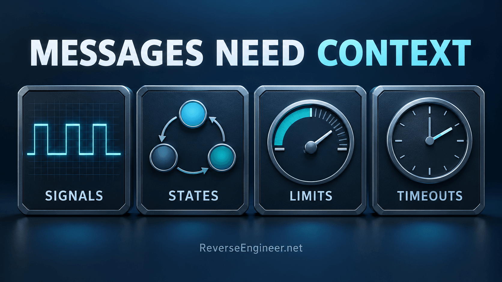
A decoded value needs a definition: units, scaling, sign, validity, freshness and the conditions under which it is meaningful. A changing field might represent a measurement, requested value, limit or state indication. Those interpretations lead to different control decisions.
For a hypothetical integration, a current limit appearing on the bus may update differently during startup, normal operation and a fault. A gateway that translates the number but drops its validity information can produce a misleading result even when its byte encoding is correct.
We therefore treat message interpretation and state reconstruction as connected work. Controlled observations, reference captures and, where appropriate, firmware analysis should support the meaning assigned to each required signal.
Document the complete communication contract
| Interface property | What needs to be established |
|---|---|
| Signal meaning | Units, scaling, sign, ranges and invalid values |
| Timing | Update expectations, freshness and timeout behaviour |
| State | Startup, ready, restricted, shutdown and fault transitions |
| Authority | Which controller supplies limits and which applies them |
| Integrity | How the implementation handles counters, checks and inconsistent messages |
| Recovery | What must happen after a reset or loss of communication |
Not every controller implements all of these mechanisms. The investigation should distinguish observed features, supported documentation and unresolved hypotheses. An engineering team needs to know which assumptions remain open before committing to gateway behaviour.
Choose where translation belongs
An adapter may translate messages between established interfaces, but it also becomes responsible for handling mismatched expectations. These can include different update rates, state models and representations of unavailable data. The design needs an explicit policy for each relevant mismatch.
In other projects, changing the vehicle controller’s interface may be preferable to adding another box. The decision depends on the software available for modification, required response time, support lifetime and how the system will be diagnosed in service.
A transparent forwarding device is only sufficient when the endpoints already agree on the semantics that matter. Once an adapter interprets state or transforms limits, its behaviour needs its own versioned specification and tests.
Validate fault handling as well as nominal communication
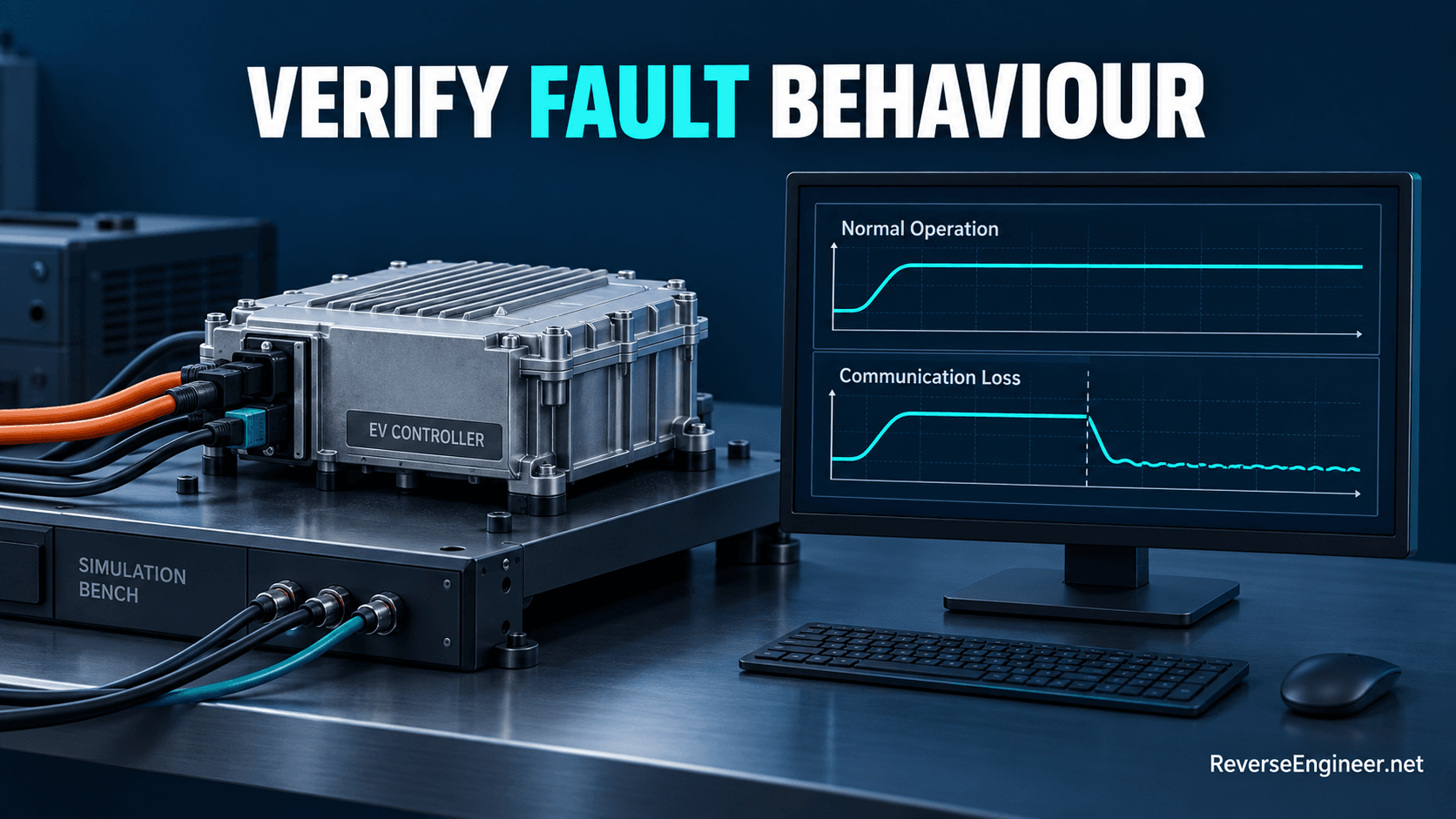
A practical test programme begins with a controlled communications environment. Recorded or simulated inputs can exercise decoding, state transitions and timeout policies without depending on a complete powertrain. Such tests should identify the assumptions made by the simulator.
Representative scenarios include stale data, a controller restarting during a session, a missing limit update and inconsistent state indications. The expected response should follow the agreed system requirements. A test should demonstrate how the integration responds, not simply whether messages continue to appear.
Further validation can then address representative hardware and system behaviour. The protocol work should preserve the intended protections and fault reporting. High-voltage commissioning, power-stage behaviour and vehicle-level acceptance belong in the wider engineering programme and should have named owners.
Deliverables that make the integration maintainable
Depending on scope, the handover can include a signal dictionary, state diagrams, a gateway mapping specification, versioned implementation code and a replayable test corpus. A machine-readable description such as a DBC may be useful for signal definitions; supplementary documentation is still needed for state-dependent behaviour.
The compatibility matrix should record firmware and hardware versions. Support for one battery-controller and inverter combination does not automatically cover another revision with a similar connector or product name.
Maintenance requirements should be agreed alongside the initial development. If a supplier changes message content or timing, the team needs a controlled method to identify the change, update the mapping and rerun the relevant tests.
Questions from EV integration teams
Can you work from captures supplied by our engineers?
Captures and existing documentation can support an initial assessment. The most useful recordings include the operating context, firmware versions and observations from the reference system. Unknown context makes apparently clear data harder to interpret.
Is the goal to reproduce an entire vehicle network?
The scope can focus on the interfaces required by the application. The engineering decision is which dependencies must be represented accurately and which are outside the intended use. That boundary should be explicit in both implementation and testing.
Discuss your BMS and inverter integration
Through our automotive control-unit analysis and firmware reverse engineering, we can assess the information needed for a custom integration. Describe your EV controller project with component references, available documents, recordings and the operational behaviour you need. We can then define the analysis, implementation and validation work as distinct deliverables.
Let's Work Together
Working on an ECU, a firmware image, or a board? Send what you have.