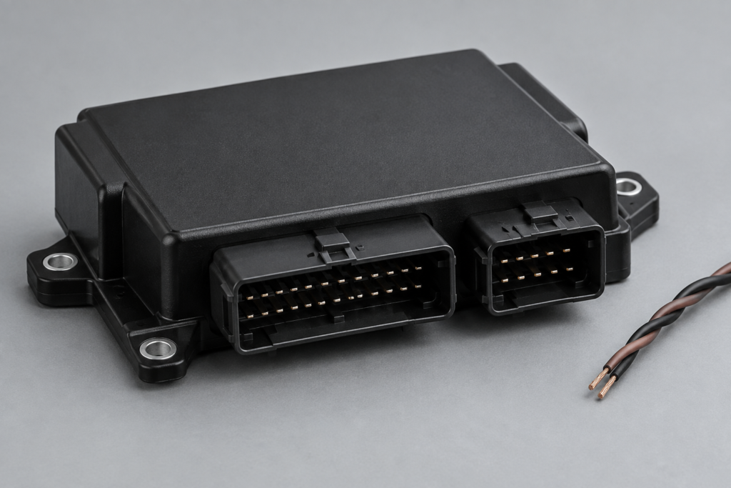
A BMW F10 with several missing control units and FlexRay faults presents an expensive diagnostic trap: the module named in a fault entry may be the receiver reporting a missing message, rather than the component that caused the communication loss. Replacing that module can leave the original problem untouched and introduce a second compatibility question.
For specialist workshops, ECU remanufacturers and integration teams, the useful next step is to localize the failure. Is one branch unavailable? Are several affected units sharing a supply or gateway dependency? Is there electrical activity without usable communication? A structured investigation turns those questions into measurements before a gateway, DME or chassis controller is condemned.
Why the fault list is only the beginning
Public discussions include an F10 report of complete FlexRay communication loss and a 2012 F10 transfer-box communication problem. These are evidence of problems owners and workshops encounter, not proof of a universal fix. Their value for a new investigation is the question they raise: which missing functions share the same dependency?
Preserve a complete vehicle scan before clearing anything. Separate currently present faults from historical entries, and record which modules still identify. Include the vehicle build information, installed equipment, gateway identification and recent work. A wiring repair, discharged battery, module replacement and software change create different starting hypotheses even when the displayed fault descriptions look similar.
Read each communication fault as a relationship: reporting controller, expected sender, missing or invalid information, and operating condition. Several receivers complaining about one sender make a different pattern from several unrelated nodes disappearing together. The scan should support a dependency map rather than become a shopping list of replacement modules.
Reconstruct the actual topology before measuring
Use the vehicle-specific wiring and diagnostic information to identify the gateway connections and affected branches. Do not transplant a diagram from a different model, production date or equipment configuration. Label every measurement with its connector, circuit and physical location so that another engineer can reproduce it.
FlexRay supports passive bus and active-star arrangements. NI’s FlexRay overview explains why topology, termination and network configuration matter. An active-star branch is not simply another tap on one continuous CAN pair. A measurement at a convenient connector therefore cannot automatically describe every branch in the vehicle.
Draw a compact map of the affected paths and their shared dependencies. Include power distribution and ground relationships as well as data wiring. If apparently separate communication failures share a power source, investigate that common dependency before assuming multiple damaged transceivers. The map should distinguish verified connections from ones inferred from incomplete records.
Separate module power from network participation
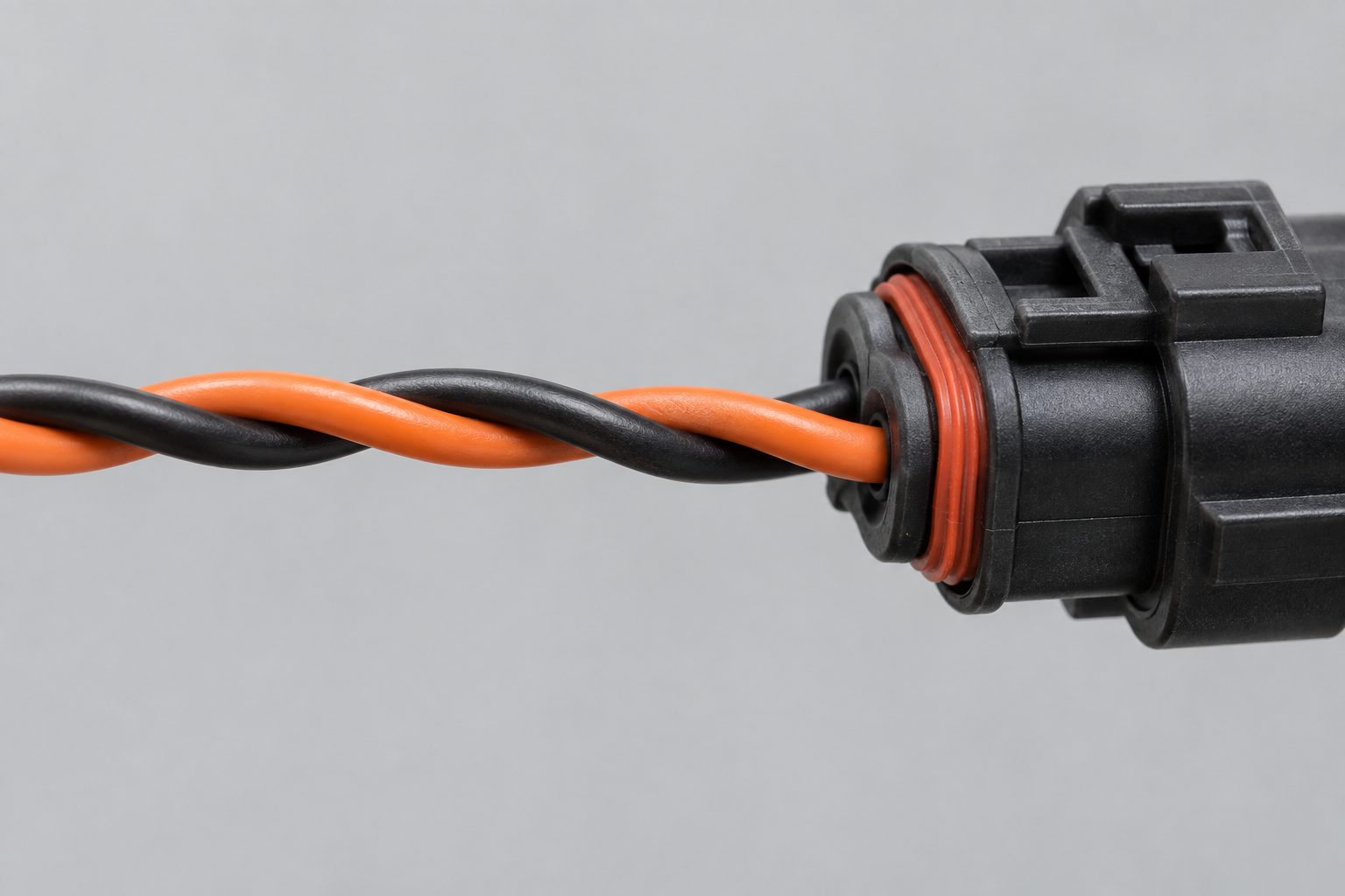
A control unit requires more than a battery feed to participate correctly. Establish the applicable supply, ground and operating-state requirements from its documentation, then measure them under the condition in which communication fails. A static check performed after the fault disappears does not characterize an intermittent reset during wake-up.
Measure voltage at a defined location with a defined reference. Record whether a reported value is a slow meter reading or a captured transient. If the communication trace and voltage recording use different time bases, document their alignment before drawing causal conclusions. A dip after a reset is not necessarily the event that caused it.
At component level, a silent transceiver need not be physically destroyed. For example, the NXP TJA1080A documentation describes operating modes, undervoltage detection and fail-silent behavior. This illustrates why supply and state evidence matter; it does not establish that this exact device is fitted to the F10 controller under investigation. Identify the actual component before applying its thresholds or pin functions.
Interpret resistance in the context of the branch
Do not apply a familiar CAN resistance rule to an unidentified FlexRay connection. First determine which branch is being measured, what remains connected and where its terminations are located. Follow the relevant power-down and measurement procedure. A resistance value without this circuit context is an observation with an unknown interpretation.
A continuity result also has limits. It can support the existence of a conductive path while leaving connector contact quality, unwanted connections and high-frequency signal behavior unresolved. Document the test conditions and compare the result with the expected circuit. Avoid declaring a harness good solely because each conductor passes a continuity check.
Where a branch isolation test is appropriate under the service procedure, record its effect on the remaining network. Removing a node can also remove a termination or alter startup behavior, so an improvement or deterioration needs interpretation. The test must have a predicted outcome for each hypothesis; unplugging modules without a topology model produces ambiguous evidence.
Distinguish electrical activity from valid communication
An oscilloscope can show that a line is active, but activity alone does not demonstrate valid frames, correct timing or successful participation. Record the probing arrangement and the point observed. Compare differential behavior and individual-line behavior where the measurement setup supports it, while accounting for instrument loading and reference limitations.
A decoder introduces a separate configuration dependency. Confirm that the capture interface, channel and timing settings match the network being observed. If a known-active branch produces an empty log, validate the acquisition before interpreting the log as vehicle silence. Keep the raw capture alongside any decoded export so that the interpretation can be revisited.
For FlexRay, participation depends on configured timing and synchronization, not just the nominal bit rate. NI describes the scheduled communication cycle and shared network parameters. Consequently, a powered ECU on a bench can remain unavailable even when its hardware is intact. Bench behavior is meaningful only when the required network context is established.
Compare gateway evidence with branch evidence
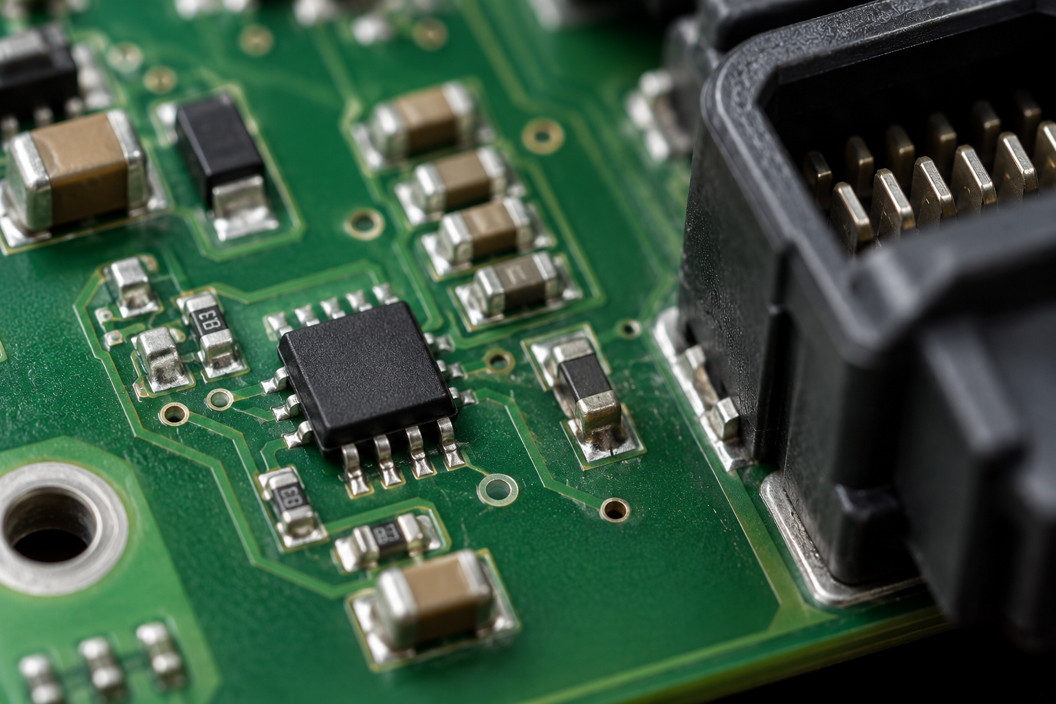
A gateway-related fault should trigger a comparison between what the diagnostic system reports and what is observed on the affected paths. Record gateway identification, relevant fault status and which other communication routes remain functional. The ability to identify the gateway does not establish that every physical interface or routed diagnostic path is healthy.
If only one documented branch is affected, investigate its local supply, wiring, connected nodes and gateway-side interface. If several branches fail together, prioritize shared dependencies while retaining the possibility of multiple faults. This is hypothesis ranking, not a guarantee that the common component is defective.
Configuration becomes especially relevant after a replacement or retrofit. Preserve the before-and-after identification and configuration records, then compare them against the intended vehicle setup. This article addresses fault localization; it does not prescribe universal port-opening commands or treat initialization as a repair for a damaged circuit. Any service function must be applicable to the specific vehicle and observed state.
Build a falsifiable fault assessment
A strong report states what would disprove each proposed cause. For a harness hypothesis, define the electrical observation expected at each end of the suspect path. For a supply hypothesis, define the correlation required between voltage behavior and loss of communication. For a module hypothesis, identify the conditions under which the unit should participate and which of those conditions have been demonstrated.
Known-good comparisons are valuable when their differences are documented. A donor with a similar label but different hardware or software is not a controlled reference. Where possible, compare the affected and reference units under the same verified conditions and retain the identification of both. An unexplained successful substitution can localize a problem without proving exactly which internal function failed.
The final assessment should distinguish confirmed defects, probable causes and unresolved alternatives. Examples of useful conclusions include a reproducible connector-dependent interruption or a branch that remains electrically abnormal with its downstream harness isolated under an approved procedure. These are measurable findings. “FlexRay is broken” does not support a repair or purchasing decision.
When ECU reverse engineering adds commercial value
Standard diagnostic procedures should resolve ordinary wiring and configuration issues first. Specialist work becomes appropriate when repeatable evidence points inside a controller, when a remanufacturer needs a reliable acceptance test, or when an integration project lacks sufficient documentation to establish the required network behavior.
A targeted engagement can define the communication hardware boundary, correlate firmware state with observed network behavior, or develop a documented test setup for the identified variant. The scope should specify which unit and software versions are covered, which reference hardware is available and how the result will be validated. It should not promise that one recovered configuration applies to every F10.
Useful deliverables may include an annotated dependency map, measurement records, trace interpretation and a repeatable fault-isolation or acceptance procedure. For a remanufacturing business, this can be more valuable than a single replacement recommendation: it creates evidence the team can use when deciding whether another returned unit is defective or merely being tested in an incomplete environment.
Discuss an unresolved BMW F10 FlexRay fault
Our ECU reverse engineering services can support a focused investigation where vehicle diagnostics and electrical testing leave an unresolved controller or network question. We scope the work around the decision your team needs to make, the evidence already available and the validation equipment required.
Contact ReverseEngineer.net with the complete scan, vehicle build and equipment details, module identification, relevant wiring references and a record of recent changes. Include measurements and raw captures where available, with their connection points and test conditions. Describe which modules remain accessible and whether the failure is permanent, intermittent or limited to a particular operation.
Let's Work Together
Working on an ECU, a firmware image, or a board? Send what you have.