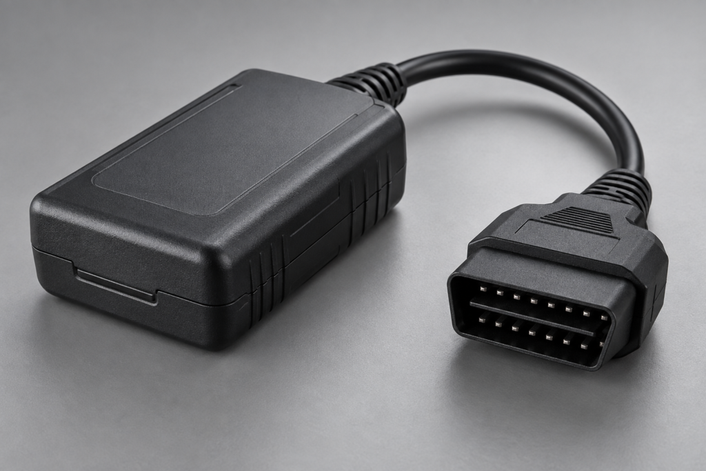
A Toyota ECU that communicates normally during diagnosis can still fail when programming begins. The programming session exercises a different sequence of software, interface and vehicle states. A workshop may see only a Calibration Update Wizard error, while the underlying failure sits in the PC-to-interface connection, a transport exchange, an ECU prerequisite or the power supply.
For remanufacturing businesses and diagnostic-tool developers, repeated failures across a defined vehicle population deserve more than another cable trial. The useful engineering result is a supported explanation of where the sequence breaks, which configuration reproduces it and how a correction can be validated. This article focuses on that failure analysis. Physical recovery after a destructive interruption is a separate question, covered in our Toyota Hilux GD interrupted-flash assessment.
Start with the actual failure, not the progress percentage
A publicly indexed Toyota reprogramming discussion describes a Calibration Update Wizard failure when changing to programming mode. The report includes a particular interface, driver and software combination. It establishes a real customer problem, but it does not establish the cause or demonstrate that another ECU with the same message needs the same repair.
A progress bar is a user-interface abstraction. Its percentage does not identify a flash address, prove that an erase completed or distinguish a local software timeout from an ECU refusal. Preserve the full error text, the application version, the last visible operation and the preceding events. The key question is what the system actually attempted and what evidence shows it completed.
Build an event timeline with separate columns for application activity, interface status, observed vehicle traffic and voltage observations. If the sources use different clocks, retain their original timestamps and document any alignment offset. Otherwise, an apparent ECU reset may be incorrectly placed before a host failure that actually triggered the interruption.
Freeze the complete J2534 configuration
Toyota’s J2534 reprogramming guidance explicitly ties validation to specific devices, firmware, DLLs and APIs. A familiar interface brand alone is not a validated configuration. The applicable device matrix and vehicle procedure should be checked at the time of the investigation rather than copied from an old successful job.
The configuration record should identify the PC operating system, Toyota application and update-wizard versions, selected vehicle interface, driver package, interface firmware and physical connection. Record the installed components before updating them. Replacing software first can remove the very combination needed to reproduce an intermittent defect and make a successful retry difficult to explain.
Distinguish the selected interface from other drivers merely installed on the PC. An inventory of several J2534 packages does not show which one the application loaded. Where supported diagnostic logs expose that information, preserve the actual selection and version. If the host cannot open its selected device, changing ECU calibration data is not a response to the demonstrated fault.
Split the investigation into host, interface and ECU evidence
At the host boundary, determine whether the application can enumerate and open the intended interface. At the vehicle boundary, determine whether the expected request appears on the observed bus and whether a response returns. These observations are related, but neither substitutes for the other. A local success indication does not by itself prove that the ECU accepted an application-level request.
If the PC reports a request was submitted but no corresponding traffic is captured, first validate the capture location and configuration. An incorrect channel or filter can create a false absence. Once the observation is trustworthy, the investigation can focus on the interval between application submission and actual transmission rather than immediately blaming the ECU.
Conversely, if a response is visible on the bus but the application reports a timeout, investigate the return path, matching criteria and timing evidence. The response may be unrelated, incomplete or later than the permitted interval. Avoid concluding that the driver dropped it until the captured response is associated with the exact outstanding request.
Use transport reconstruction only where the capture supports it
For a confirmed ISO-TP-over-CAN exchange, evaluate the reconstructed diagnostic message rather than treating every CAN frame as a complete command. A transport analysis should preserve frame order, addressing context and timestamps. Identify gaps or capture overruns before interpreting a partially reconstructed payload as an ECU error.
The Linux kernel ISO-TP documentation describes the distinction between single-frame messages and segmented transfers using First, Consecutive and Flow Control frames. In a relevant capture, block size and minimum separation time help explain the expected exchange. They should be decoded from the observed session rather than assigned guessed values. This reference explains transport mechanics; it does not establish that Toyota software uses the Linux implementation.
A technically useful report states whether a failure was observed before request transmission, during transport, after a complete request or while waiting for a subsequent operation. It should identify the evidence supporting that classification. Do not impose one protocol interpretation on every Toyota model merely because the same PC application is involved; the target and session determine what needs decoding.
Where the diagnostic protocol and response format have been established, an explicit ECU rejection is stronger evidence than a generic timeout. Preserve the request-response pair and interpret it against the applicable protocol and ECU behavior. A negative response can narrow the investigation without proving that hardware is damaged or that a security feature must be changed.
Separate programming prerequisites from communication defects
Toyota’s T-SB-0107-20 Rev2 describes a security-signature workflow for its stated vehicle applicability. It also specifies interface selection within GTS+. This is evidence that programming initialization has software and authorization prerequisites; it is not a statement that every older CUW workflow follows the same sequence.
When initialization fails, establish the applicable Toyota procedure, current ECU identification and intended calibration. Document whether the failure occurred during preparation, authorization, entry to programming or a later operation. Treat the presence of a signature requirement as a compatibility and workflow fact. A transport investigation should not silently become an attempt to bypass it.
Toyota also maintains a Techstream known-bugs reference containing version- and vehicle-specific reports. Historical entries can suggest a testable explanation, but their dates and applicability matter. A similar error phrase is not enough to apply an old workaround to a different platform.
Measure the supply condition relevant to the ECU
A charger display or an average voltage reading does not establish the instantaneous supply at an ECU connector. A voltage investigation should state the measurement location, reference point, instrument limitations and timing relative to the observed failure. Without that context, “voltage was stable” may mean only that a slow display did not show a brief disturbance.
Use the applicable manufacturer procedure to define power-support requirements. Do not substitute a universal voltage or current value from another vehicle. For engineering correlation, distinguish an externally measured supply disturbance from an ECU reset inferred through communication loss. The latter could have several causes, and a missing response alone does not prove a brownout.
A controlled test can compare the event sequence under a corrected, documented supply arrangement without changing the software stack simultaneously. If the failure disappears, repeatability and additional observations still matter before assigning root cause. A single successful run supports a hypothesis; a documented comparison across the relevant conditions supports a deployment decision.
Design a comparison that can actually isolate the cause
A useful comparison changes one meaningful variable while preserving the rest: the approved interface configuration, host environment or connection arrangement. Define the observation sought before running it. For example, the question may be whether an interface disconnect occurs before the ECU stops responding, rather than whether a second attempt happens to reach a larger percentage.
Do not use repeated destructive programming as a general-purpose diagnostic loop. The manufacturer’s current failure-handling procedure determines the permitted next action for the state reached. If an erase or write may have occurred, retain that uncertainty in the record and assess recovery prerequisites before introducing another experimental configuration.
For a tool-development team, the final regression test should reproduce the relevant boundary condition using an appropriate development or controlled test environment. Record both the former failure and the corrected behavior. A useful acceptance criterion is a specified sequence completing on the stated configuration with consistent post-operation identification, not simply the absence of a dialog box.
What a specialist investigation should deliver
A paid investigation should turn scattered logs into an actionable engineering package. That can include a reproducible environment description, synchronized event timeline, decoded exchanges where supported, a ranked fault assessment and a validation plan. Every conclusion should point to the observation that supports it, with unresolved alternatives kept visible.
The commercial scope depends on the buyer. A workshop group may need to determine whether an approved equipment combination is reliable for a particular ECU family. A remanufacturer may need to separate a board defect from a programming-station defect. A diagnostic-tool vendor may need a reproducible transport issue that its developers can fix. These require different deliverables and should not be priced as the same routine software update.
ReverseEngineer.net can scope these questions through our ECU reverse engineering services. The engagement should identify the affected hardware and software versions, available evidence and desired decision before deeper analysis begins. It should also define what successful validation will look like for your team.
Contact ReverseEngineer.net with the ECU identification, applicable vehicle details, exact error, complete tool-version list and untouched logs. Include any authorized bus capture, measurement record and known-good comparison, plus whether the failure occurs before or after programming begins. This allows a proposal to target the unresolved engineering problem rather than repeat checks your team has already completed.
Let's Work Together
Working on an ECU, a firmware image, or a board? Send what you have.