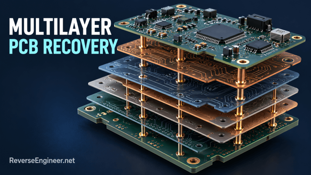
An obsolete circuit board can threaten the service life of an otherwise valuable product. The manufacturer may no longer supply replacements, the design files may be missing, or a critical component may have reached end of life. Multilayer PCB reverse engineering can recover the engineering information needed to assess a replacement, redesign the board and restore a maintainable production record.
The objective is more demanding than producing a board that looks similar. A replacement must satisfy electrical, mechanical and functional requirements within the system where it will operate.
Define what must survive the redesign
Start with the product’s constraints. Must the board fit the same enclosure and connectors? Does existing firmware have to run unchanged? Are analog accuracy, communication timing or compatibility with installed accessories essential? These questions determine whether the project is a reproduction, a component substitution or a more substantial redesign.
For example, an industrial instrument may need a compatible replacement controller while retaining its sensor assembly and service software. Recovering the connectors is only the beginning. The project may also need to preserve calibration storage, startup behaviour, measurement timing and the data expected by the host application.
Why multilayer PCB recovery needs more than photographs
Surface images document placement, markings and visible routing, but internal connections can remain hidden. Dense packages, buried connections and planes complicate the reconstruction. A useful plan combines available manufacturing records, component documentation and measurements, then selects additional inspection methods according to the board and the evidence gaps.
Some investigations may benefit from specialist imaging or analysis of a sacrificial sample. That decision should be made explicitly because sample availability and the need to preserve working units affect the approach. A recovered connection should carry a confidence level until it is supported by suitable evidence.
Recover a coherent design record
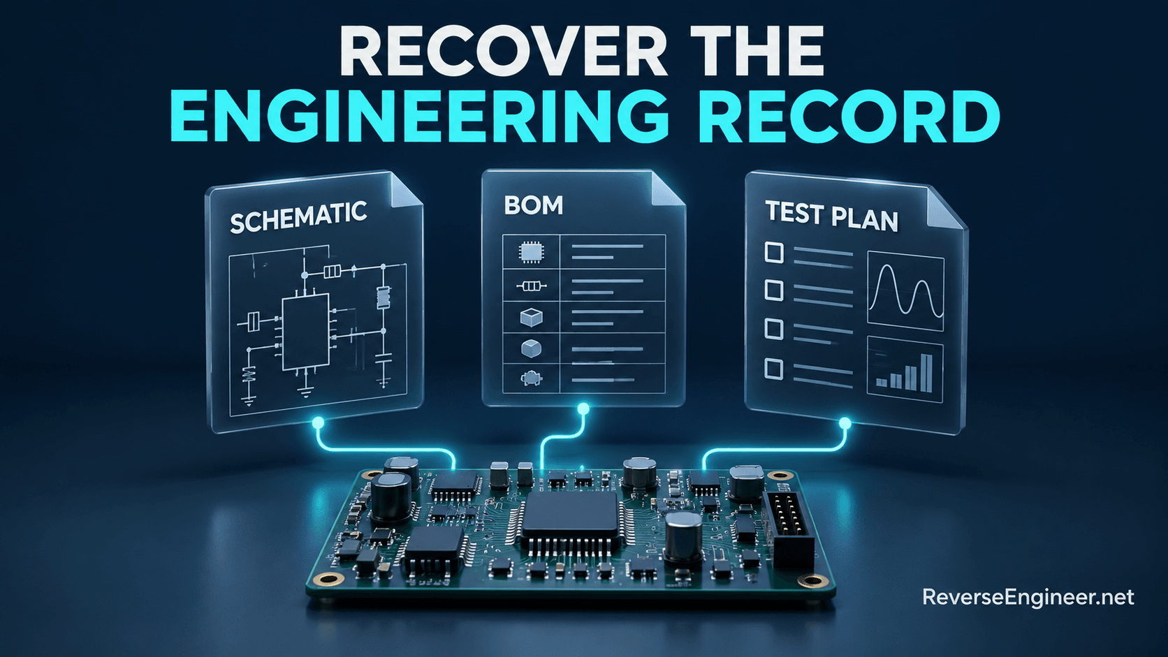
The schematic, bill of materials and physical layout answer related but different questions. Connectivity describes which nodes are joined. The schematic explains functional relationships. The bill of materials identifies the intended components and important characteristics. The layout records how the physical implementation addresses mechanical and electrical constraints.
| Recovered asset | Why it matters |
|---|---|
| Schematic and net connectivity | Supports circuit understanding, modification and fault analysis. |
| Bill of materials with uncertainty notes | Separates identified components from assumptions requiring confirmation. |
| Mechanical and connector definition | Preserves fit and interfaces to the surrounding product. |
| Programmable-device inventory | Identifies firmware, configuration and provisioning dependencies. |
| Verification plan | Defines the evidence required before accepting a replacement. |
Component substitution is an engineering decision
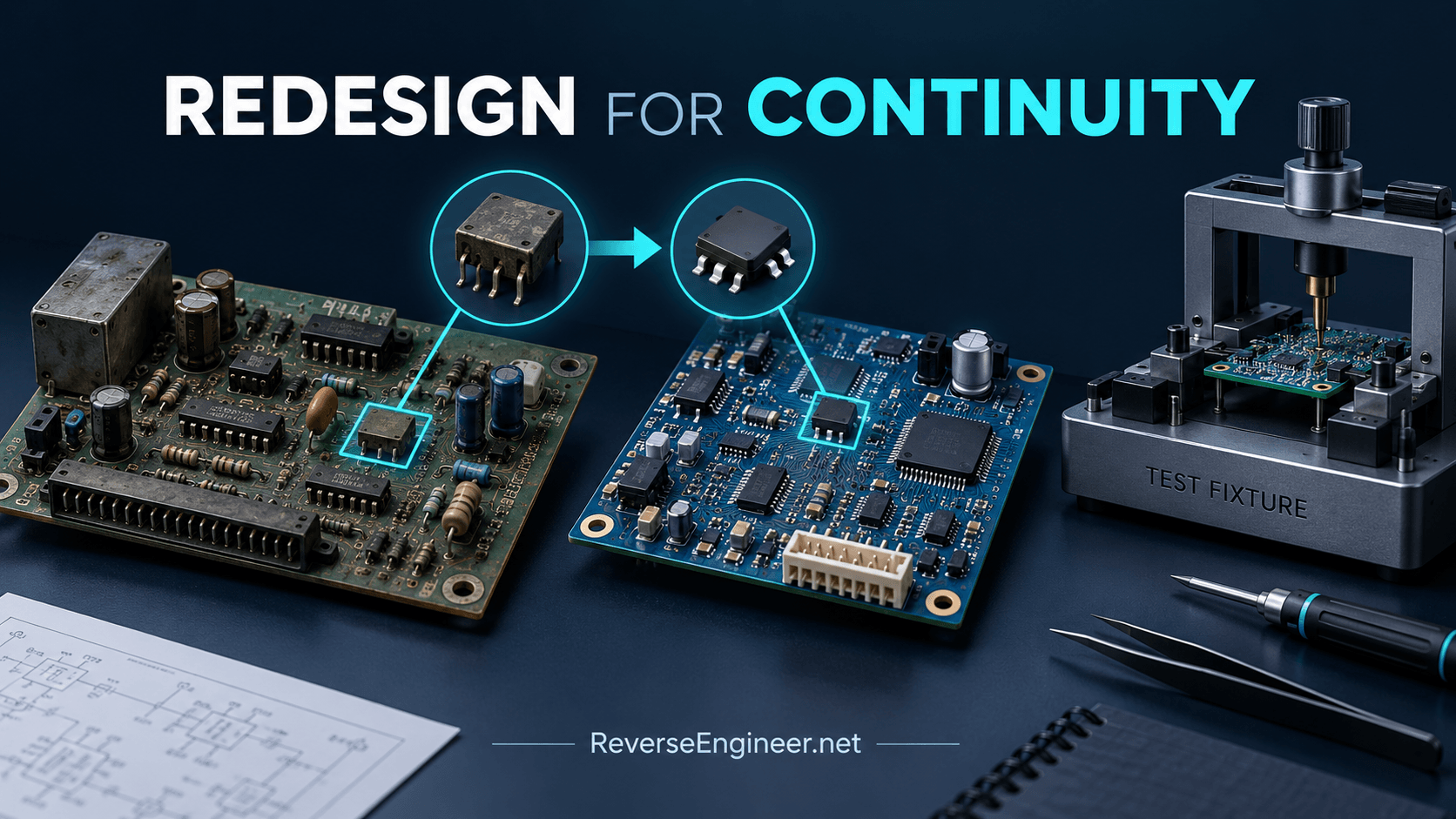
A replacement component may share a package and headline rating while differing in startup behaviour, tolerance, timing or operating limits. Evaluate it in the actual circuit. Changes to a regulator, memory, oscillator or interface device can affect assumptions elsewhere on the board.
Supplier lifecycle information helps prioritize the redesign. For example, Texas Instruments publishes product lifecycle status categories that distinguish active products from those approaching or past withdrawal. The practical step is to check the status of proposed parts and record the supply assumptions behind the new bill of materials.
Where a key function depends on an unavailable custom device, the project may require functional replacement rather than a direct substitution. That can turn a board recovery job into a combined hardware and firmware development effort. Discovering this early makes the commercial scope more realistic.
Include firmware and calibration in the feasibility study
A complete-looking PCB can remain unusable if its programmable devices contain unavailable code or configuration. Inventory microcontrollers, programmable logic, serial memories and device-specific data. Establish which artifacts are available and which must be recovered, recreated or supplied by the customer.
Keep production calibration separate from executable firmware where the product requires that distinction. A replacement board may need its own calibration procedure rather than copied values from a reference unit. The proposed manufacturing process should explain how each unit becomes ready for service.
Validate the replacement at board and system levels
Electrical checks establish whether the candidate behaves as expected under defined conditions. System checks establish whether the surrounding product accepts that behaviour. Both matter. A communication interface can appear correct in isolation while failing during a particular startup sequence or under the loading of the installed harness.
Define acceptance criteria for the relevant power states, interfaces, accuracy, timing and environmental conditions. The product’s responsible team should determine which existing qualification requirements need to be repeated after the change. A recovered schematic is an engineering input, not evidence that a new assembly inherits all prior approvals.
Plan for production, not only a working prototype
A successful prototype should lead to a usable handover: editable design files, a controlled bill of materials, manufacturing outputs and a repeatable test process. Specify the tools and file formats expected by the customer’s engineering and manufacturing teams before the project starts.
Document unresolved substitutions, assembly variants and inspection requirements. If production testing requires a fixture or programming step, include it in the scope. Otherwise, the project can finish with a working demonstration but leave the customer without a repeatable way to build and accept further units.
What makes an obsolescence project complex?
Layer count alone does not determine effort. Inaccessible connections, mixed analog and digital functions, high-speed interfaces, missing programmable content and limited reference samples can dominate the investigation. The required service life and intended production volume also affect whether exact reproduction or redesign is the better investment.
Our hardware reverse engineering services provide a starting point for evaluating these dependencies. A first phase can establish what is recoverable, what remains uncertain and which replacement route deserves detailed development.
Discuss your obsolete electronics
Contact ReverseEngineer.net with clear board photographs, available schematics or manufacturing files, known component shortages and the number of working samples. Describe the product interfaces that must remain compatible, the expected production or service volume and the required handover. That context allows the project to be scoped around continuity of supply rather than a visual copy of the board.
Let's Work Together
Working on an ECU, a firmware image, or a board? Send what you have.